
Use our free Motor & Pulley RPM Calculator to estimate AC induction motor speed, calculate driven pulley RPM, and determine pulley speed ratios and theoretical belt speed. Choose Motor RPM or Pulley Speed mode, enter the required values, and get instant results in metric or imperial units.
Not sure where to find your motor’s frequency, number of poles, slip percentage, or pulley diameters? We’ve included a complete step-by-step guide below the calculator explaining every input, where to find the correct measurements, the calculation formulas, and practical examples to help you use the tool accurately.
Motor RPM & Pulley Speed Calculator
Estimate AC induction-motor RPM from frequency, poles and slip, or calculate driven pulley speed from a belt-drive ratio.
Loading calculator… If it does not appear, please enable JavaScript.
How the calculation works
Formula: Induction motor: synchronous RPM = 120 × frequency (Hz) ÷ number of poles; estimated loaded RPM = synchronous RPM × (1 − slip fraction). Pulley: driven RPM = driver RPM × driver pitch diameter ÷ driven pitch diameter.
Important: Motor mode applies to AC induction motors, not universal, brushless DC or stepper motors. Pulley mode assumes negligible belt slip and correct pitch diameters.
What Is a Motor & Pulley RPM Calculator?
A Motor & Pulley RPM Calculator is a free online tool that helps you estimate electric motor speed, calculate pulley output RPM, and understand how pulley diameters affect the rotational speed of belt-driven equipment.
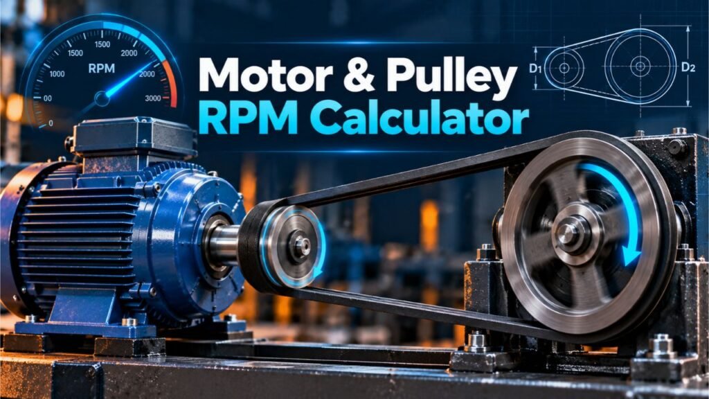
If you’re working with an electric motor, belt-driven machine, workshop tool, or mechanical power transmission system, knowing the relationship between motor RPM and pulley size can help you understand how the equipment operates.
Our calculator provides two separate calculation modes:
- Motor RPM Calculator: Estimates the operating speed of an AC induction motor using electrical frequency, motor pole count, and slip percentage.
- Pulley Speed Calculator: Calculates driven pulley RPM, speed multiplier, and theoretical belt speed using the driving shaft RPM and pulley diameters.
Both modes are designed for straightforward calculations, with metric and imperial measurement options.
For example, you can use the calculator to find the approximate speed of a four-pole induction motor operating at 60 Hz or determine the output shaft speed when a 1,750 RPM motor drives a larger pulley.
However, the calculations have important limitations.
The motor calculation applies to AC induction motors, not every electric motor design. The pulley calculation assumes an ideal belt drive without belt slip or other transmission losses.
This guide explains how to identify every required input, where to find motor and pulley specifications, how the formulas work, and how to interpret the results.
How to Use the Motor RPM Calculator
The Motor RPM mode estimates the loaded rotational speed of an AC induction motor.
It requires three inputs:
- Supply or drive frequency.
- Total number of motor poles.
- Assumed motor slip percentage.
Let’s examine each step.
Step 1: Select Motor RPM Mode
Open the calculator above and select the Motor RPM tab.
This mode is intended specifically for AC induction motors.
It calculates synchronous speed and then adjusts that value using the entered slip percentage.
Step 2: Enter the Motor Frequency
Find the field labeled Supply / Drive Frequency.
Enter the electrical frequency in Hertz (Hz).
Common examples include:
- 60 Hz.
- 50 Hz.
- 30 Hz from a suitably configured variable frequency drive.
- Other frequencies within the motor and drive manufacturer’s permitted operating range.
For a typical motor operating directly from the US power grid, the rated frequency is commonly 60 Hz.
If the motor is connected through a variable frequency drive (VFD), use the frequency actually supplied to the motor by the drive for the operating condition being evaluated.
Do not automatically use the wall power frequency when a VFD is changing the motor’s operating frequency.
Step 3: Select the Number of Motor Poles
The next field is Total Motor Poles.
The calculator provides the following options:
- 2 poles.
- 4 poles.
- 6 poles.
- 8 poles.
- 10 poles.
- 12 poles.
The number of magnetic poles is a characteristic of the motor’s electrical design.
It affects the synchronous rotational speed produced at a given electrical frequency.
For example, at 60 Hz:
- A two-pole motor has a synchronous speed of 3,600 RPM.
- A four-pole motor has a synchronous speed of 1,800 RPM.
- A six-pole motor has a synchronous speed of 1,200 RPM.
Important: Enter the total number of poles, not the number of pole pairs.
A four-pole motor has two pole pairs, but the calculator requires the number 4.
Step 4: Enter the Motor Slip Percentage
The next field is Assumed Motor Slip.
Slip describes the percentage by which an induction motor’s rotor speed falls below the synchronous speed of the rotating magnetic field.
For example, if you want to calculate the speed assuming 3% slip, enter:
Slip = 3
Do not enter 0.03 when the field asks for a percentage.
The correct slip depends on the motor’s design, operating load, and other conditions.
If you know the motor’s rated full-load RPM, you can calculate its rated slip using the formula explained later in this article.
If you do not know the slip, the result is only an estimate based on the assumption you enter.
Step 5: Review the Motor Speed Results
The calculator displays:
| Result | What it means |
|---|---|
| Estimated Loaded Motor Speed | Calculated rotor RPM after allowing for the entered slip |
| Synchronous Speed | Theoretical speed of the rotating magnetic field |
| Slip From Synchronous | Difference between synchronous and estimated rotor RPM |
| Slip Assumption | Slip percentage entered in the calculator |
Compare the results with the motor manufacturer’s specifications.
The calculated loaded speed is not guaranteed to match the motor’s actual RPM at every operating load.
Where Can You Find Motor Frequency, Poles, and Slip?
Finding reliable input values is one of the most important parts of using this calculator.
Fortunately, you can often find much of the information on the electric motor’s nameplate or in its technical documentation.
1. Where to Find Motor Frequency (Hz)
Most industrial AC motors have an identification plate attached to their housing.
This is called the motor nameplate.
It usually contains electrical and mechanical specifications.
Look for a field labeled:
- HZ
- Hz
- Frequency
- Rated Frequency
For example, a nameplate might list:
| Nameplate specification | Example |
|---|---|
| Motor power | 2 HP |
| Rated voltage | 230 V |
| Frequency | 60 Hz |
| Rated speed | 1,750 RPM |
| Phase | 3 |
For this example, the rated frequency is 60 Hz.
If the motor operates directly from the rated-frequency supply, you can enter 60 into the frequency field.
However, if a VFD supplies a different frequency to the motor, use the actual drive output frequency for the operating point you want to evaluate.
2. Where to Find the Number of Motor Poles
Some motor nameplates or product specifications directly identify the number of poles.
You may see:
Poles: 4
In that case, select 4 in the calculator.
If the pole count is not printed, check:
- The motor manufacturer’s product page.
- The motor specification sheet.
- The motor model number and corresponding catalog.
- The manufacturer’s technical drawing.
- The equipment service documentation.
You can sometimes infer the likely pole count by comparing the rated motor RPM with standard synchronous speeds.
For example, a conventional 60 Hz induction motor with a rated full-load speed near 1,750 RPM is typically a four-pole motor.
Its synchronous speed is 1,800 RPM.
Likewise, a motor rated near 3,450 RPM at 60 Hz is commonly a two-pole induction motor.
This is useful for identifying common motor configurations, but it is not a substitute for confirming the actual motor design.
3. Where to Find Motor Slip Percentage
Motor slip percentage is not always printed directly on the nameplate.
However, it can be calculated if you know:
- The motor’s synchronous speed.
- The motor’s actual or rated loaded speed.
The formula is:
Slip (%) = [(Synchronous RPM − Actual RPM) ÷ Synchronous RPM] × 100
For example, suppose you have:
- Motor frequency: 60 Hz.
- Motor poles: 4.
- Rated full-load speed: 1,750 RPM.
First, calculate synchronous speed:
Synchronous RPM = (120 × 60) ÷ 4
Synchronous RPM = 1,800
Next, calculate slip:
Slip = [(1,800 − 1,750) ÷ 1,800] × 100
Slip ≈ 2.78%
You can enter approximately 2.78 in the slip field.
The calculator will then estimate the motor speed near 1,750 RPM.
This example represents rated full-load slip. Actual slip changes with load.
4. What If the Motor Nameplate Is Missing?
If the motor has no readable nameplate, identifying its exact characteristics may be difficult.
Try checking the equipment manual, manufacturer’s catalog, motor model number, or an existing maintenance record.
Do not infer motor frequency, pole count, or operating limits from physical appearance alone.
If accurate identification is necessary for maintenance or equipment changes, consult the motor manufacturer or a qualified technician.
5. Where to Find Motor RPM Directly
If you already know the motor’s actual shaft speed, you may not need Motor RPM mode.
For example, a motor nameplate may specify:
Rated Speed: 1,725 RPM
This is useful when estimating pulley output speed at the rated operating condition.
Enter the appropriate motor shaft RPM directly into Pulley Speed mode.
Remember that nameplate RPM generally represents the rated full-load condition. The actual operating RPM may differ depending on load and control settings.
For higher-accuracy measurements, qualified personnel may use suitable tachometer equipment under approved machine-safety procedures.
AC Motor RPM Calculation Formula
The basic synchronous speed formula is:
Synchronous RPM = (120 × Frequency) ÷ Number of Poles
It can also be expressed as:
Ns = (120 × f) / P
Where:
- Ns = synchronous speed in RPM.
- f = supply or drive frequency in Hertz.
- P = total number of motor poles.
- 120 = conversion constant.
The 120 constant comes from converting electrical cycles per second into mechanical revolutions per minute while accounting for pole pairs.
Loaded Induction Motor Speed Formula
An induction motor generally runs below synchronous speed when producing torque.
To estimate rotor speed:
Motor RPM = Synchronous RPM × (1 − Slip ÷ 100)
For example, with 3% slip:
Motor RPM = Synchronous RPM × 0.97
This formula assumes you already know or have reasonably estimated the slip for the operating condition.
How to Calculate the Slip in RPM
You can also calculate the difference between synchronous speed and rotor speed:
Slip Speed (RPM) = Synchronous RPM − Rotor RPM
For example:
Synchronous Speed = 1,800 RPM
Actual Speed = 1,746 RPM
Slip Speed = 1,800 − 1,746
Slip Speed = 54 RPM
The slip percentage is:
54 ÷ 1,800 × 100 = 3%
Calculate Motor RPM at 60 Hz
The following table shows synchronous speeds at 60 Hz.
| Number of poles | Synchronous RPM |
|---|---|
| 2 | 3,600 |
| 4 | 1,800 |
| 6 | 1,200 |
| 8 | 900 |
| 10 | 720 |
| 12 | 600 |
These are theoretical synchronous speeds, not guaranteed full-load induction motor speeds.
Calculate Motor RPM at 50 Hz
For a 50 Hz supply:
| Number of poles | Synchronous RPM |
|---|---|
| 2 | 3,000 |
| 4 | 1,500 |
| 6 | 1,000 |
| 8 | 750 |
| 10 | 600 |
| 12 | 500 |
At the same pole count, reducing frequency from 60 Hz to 50 Hz reduces synchronous speed proportionally.
However, changing motor operating frequency must be done within the motor and drive manufacturer’s permitted operating conditions.
Motor RPM Calculation Examples
Example 1: Four-Pole AC Motor at 60 Hz
Suppose an AC induction motor has:
| Parameter | Value |
|---|---|
| Frequency | 60 Hz |
| Number of poles | 4 |
| Assumed slip | 3% |
Calculate synchronous speed:
Ns = (120 × 60) ÷ 4
Ns = 1,800 RPM
Calculate estimated loaded speed:
Motor RPM = 1,800 × (1 − 3/100)
Motor RPM = 1,800 × 0.97
Estimated Motor RPM = 1,746
The difference is:
1,800 − 1,746 = 54 RPM
Results:
- Synchronous speed: 1,800 RPM.
- Estimated loaded speed: 1,746 RPM.
- Slip speed: 54 RPM.
- Assumed slip: 3%.
Example 2: Six-Pole Motor at 50 Hz
Suppose:
- Frequency: 50 Hz.
- Poles: 6.
- Assumed slip: 4%.
Synchronous RPM = (120 × 50) ÷ 6
Synchronous RPM = 1,000
Estimated loaded RPM = 1,000 × 0.96
Estimated Motor RPM = 960 RPM
Again, this is a theoretical example based on the selected slip.
Example 3: Calculate Motor Slip From Nameplate RPM
Consider a four-pole, 60 Hz induction motor with a rated speed of 1,725 RPM.
Synchronous speed = 1,800 RPM.
Slip = [(1,800 − 1,725) ÷ 1,800] × 100
Rated Slip ≈ 4.17%
This illustrates how a motor’s nameplate information can help determine a suitable rated slip input.
How to Use the Pulley Speed Calculator
The second mode of our calculator determines the theoretical rotational speed of a driven pulley.
It requires:
- Driver shaft RPM.
- Driver pulley pitch diameter.
- Driven pulley pitch diameter.
From these values, it calculates driven pulley RPM, speed multiplier, and theoretical belt speed.
Step 1: Select Pulley Speed Mode
Choose the Pulley Speed tab.
This mode is designed for a basic two-pulley belt-drive arrangement.
The first pulley is the driver.
The second pulley is the driven pulley.
Step 2: Enter Driver Shaft Speed
Enter the rotational speed of the driving shaft.
If the motor directly drives the first pulley, this may be the motor’s actual shaft RPM.
For example:
Driver Shaft Speed = 1,750 RPM
If the motor is connected through another gearbox or transmission before the pulley, use the actual driving pulley shaft speed rather than assuming it equals motor RPM.
Step 3: Enter Driver Pulley Pitch Diameter
The driver pulley is attached to the shaft supplying rotational power to the belt.
Enter its pitch or equivalent manufacturer-specified reference diameter in the appropriate units.
For example:
Driver Pulley Pitch Diameter = 3 inches
You can find the correct dimension in the pulley manufacturer’s product specifications.
Step 4: Enter Driven Pulley Pitch Diameter
The driven pulley receives motion from the belt.
Suppose its pitch diameter is:
Driven Pulley Pitch Diameter = 6 inches
The calculator uses the two pulley diameters to determine the ideal speed relationship.
Step 5: Review the Results
The calculator displays:
| Output | Meaning |
|---|---|
| Driven Pulley Speed | Theoretical RPM of the output pulley |
| Speed Multiplier | Driven RPM divided by driver RPM |
| Driver Pulley Speed | Entered driving shaft RPM |
| Theoretical Belt Speed | Linear belt speed assuming no slip |
A speed multiplier below 1 means the driven pulley rotates slower than the driver.
A speed multiplier above 1 means the driven pulley rotates faster.
A multiplier of 1 means both pulleys have the same theoretical RPM.
Where to Find Driver and Driven Pulley Diameters
The pulley diameter is one of the most important inputs.
However, a common mistake is assuming that the outside diameter is always the correct diameter for a speed-ratio calculation.
That is not necessarily true.
1. Identify the Driver Pulley
The driver pulley is connected to the shaft supplying motion.
For a simple motor-driven system, the pulley mounted on the motor shaft is usually the driver pulley.
For example:
Electric Motor → Driver Pulley → Belt → Driven Pulley → Machine Shaft
The driver pulley transfers rotation through the belt to the driven pulley.
2. Identify the Driven Pulley
The driven pulley is connected to the machine shaft receiving motion.
Depending on the machine, it may drive:
- A drill press spindle.
- A belt-driven fan.
- A workshop machine shaft.
- A belt-driven pump.
- Other compatible equipment.
The driven pulley may be larger or smaller than the driver pulley.
3. Check the Pulley Manufacturer’s Specifications
The best place to find the relevant diameter is the pulley or sheave manufacturer’s technical documentation.
Depending on the belt system and applicable standard, specifications may identify:
- Pitch diameter.
- Datum diameter.
- Effective diameter.
- Outside diameter.
- Pulley bore diameter.
- Groove profile.
- Number of grooves.
Pitch diameter, datum diameter, effective diameter, and outside diameter are not always interchangeable.
ISO belt-drive terminology distinguishes these measurements.
For a reliable speed-ratio calculation, use consistent, appropriate reference diameters for both pulleys.
4. Check the Pulley Part Number
Many industrial pulleys and sheaves have a part number or identification marking.
You may find it on the pulley hub or in the equipment’s parts documentation.
Use that identification to locate the manufacturer’s catalog.
A manufacturer may provide the appropriate pitch or datum dimensions for the belt system.
Do not assume that every number stamped on the pulley represents its pitch diameter.
5. Can You Measure Pulley Diameter With a Caliper?
A caliper can measure some physical pulley dimensions, including accessible outside diameters.
However, the outside diameter alone does not necessarily reveal the belt pitch diameter.
For V-belt systems, the belt’s pitch line generally lies at a position related to the groove and belt geometry.
The difference depends on the applicable pulley and belt specifications.
For a more accurate calculation:
- Identify the pulley and belt type.
- Find the manufacturer’s reference diameter.
- Use the same diameter convention for both pulleys.
- Enter the values in consistent units.
If only outside measurements are available, treat a resulting calculation as approximate unless the correct effective-diameter relationship is established.
Only inspect or measure pulleys when the equipment is stopped, isolated from power, and secured under the applicable maintenance procedure.
Never measure a rotating pulley.
6. Should You Use the Pulley Bore Diameter?
No.
The bore diameter is the opening that fits over the shaft.
For example, a pulley may have:
- Outside diameter: 6 inches.
- Shaft bore: 5/8 inch.
The 5/8-inch bore diameter is not the relevant dimension for calculating the pulley speed ratio.
You need the appropriate pitch or equivalent reference diameter.
Pulley RPM Calculation Formula
For a basic belt-drive system with negligible slip:
Driven RPM = Driver RPM × (Driver Diameter ÷ Driven Diameter)
Or:
N₂ = N₁ × (D₁ ÷ D₂)
Where:
- N₁ = driver pulley RPM.
- N₂ = driven pulley RPM.
- D₁ = driver pulley pitch diameter.
- D₂ = driven pulley pitch diameter.
The formula works with inches or millimeters as long as both diameters use the same measurement unit and reference convention.
Why Does the Formula Work?
In an ideal belt-drive system, the belt’s linear speed is the same at the pitch line of both pulleys.
Therefore:
N₁ × D₁ = N₂ × D₂
Rearranging:
N₂ = (N₁ × D₁) ÷ D₂
This gives the theoretical driven pulley RPM.
Actual belt drives can differ because of slip, creep, and operating conditions.
How to Calculate Pulley Speed Ratio
Pulley speed ratio can be expressed in different ways, so it is important to identify the convention being used.
A common reduction-ratio expression is:
Speed Reduction Ratio = Driven Diameter ÷ Driver Diameter
For example:
Driven Diameter = 6 inches
Driver Diameter = 3 inches
Reduction Ratio = 6 ÷ 3
Ratio = 2:1
This means the driver rotates twice for every revolution of the driven pulley, under ideal conditions.
Our calculator displays the inverse relationship as a Speed Multiplier:
Speed Multiplier = Driver Diameter ÷ Driven Diameter
For the same example:
Speed Multiplier = 3 ÷ 6
Speed Multiplier = 0.5×
Both expressions describe the same system, but they use different ratio conventions.
Pulley Speed Calculation Examples
Example 1: A 1,750 RPM Motor With Two Pulley Sizes
Suppose you have:
| Input | Value |
|---|---|
| Driver RPM | 1,750 |
| Driver pitch diameter | 4 inches |
| Driven pitch diameter | 8 inches |
Calculate:
Driven RPM = 1,750 × (4 ÷ 8)
Driven RPM = 1,750 × 0.5
Driven Pulley RPM = 875
The driven pulley rotates at half the speed of the driver in this ideal calculation.
The speed multiplier is 0.5×.
Example 2: Increasing Output Speed With a Smaller Driven Pulley
Now consider:
- Driver RPM: 1,750.
- Driver pulley diameter: 8 inches.
- Driven pulley diameter: 4 inches.
Driven RPM = 1,750 × (8 ÷ 4)
Driven RPM = 1,750 × 2
Driven Pulley RPM = 3,500
Here, the driven pulley theoretically rotates twice as fast as the driver.
This is a speed-increasing arrangement.
However, increasing the theoretical output RPM does not mean the driven machine can safely operate at that speed.
The output shaft, bearings, accessories, guards, and other components must be rated for the operating conditions.
Example 3: Metric Pulley Speed Calculation
Suppose:
- Driver RPM: 1,455.
- Driver pitch diameter: 100 mm.
- Driven pitch diameter: 250 mm.
Driven RPM = 1,455 × (100 ÷ 250)
Driven RPM = 1,455 × 0.4
Driven Pulley RPM = 582
The driven pulley rotates at 40% of the driver speed.
Example 4: Combining Motor RPM and Pulley Calculations
This example demonstrates how the two modes work together.
First, calculate an AC induction motor’s estimated operating RPM.
Motor specifications:
- Frequency: 60 Hz.
- Poles: 4.
- Assumed slip: 3%.
Synchronous RPM:
(120 × 60) ÷ 4 = 1,800
Estimated motor RPM:
1,800 × 0.97 = 1,746
Now suppose this motor drives a pulley system with:
- Driver pitch diameter: 3 inches.
- Driven pitch diameter: 6 inches.
Driven RPM:
1,746 × (3 ÷ 6) = 873
Combined Results:
| Calculation | Result |
|---|---|
| Synchronous motor speed | 1,800 RPM |
| Estimated loaded motor speed | 1,746 RPM |
| Ideal pulley speed multiplier | 0.5× |
| Ideal driven pulley speed | 873 RPM |
This is a theoretical calculation combining an assumed motor slip with an ideal belt-drive ratio.
Actual output RPM may differ.
How to Calculate Belt Speed
The pulley calculator also displays theoretical belt speed.
Belt speed represents the linear velocity of the belt traveling around the pulleys.
This is different from pulley RPM.
RPM measures rotational motion.
Belt speed measures linear movement.
Belt Speed Formula (Imperial)
When pulley diameter is measured in inches:
Belt Speed (ft/min) = (π × Driver Diameter × Driver RPM) ÷ 12
The calculator may display feet per minute as SFM.
Belt Speed Formula (Metric)
When diameter is measured in millimeters:
Belt Speed (m/min) = (π × Driver Diameter × Driver RPM) ÷ 1,000
To convert from meters per minute to meters per second:
Belt Speed (m/s) = Belt Speed (m/min) ÷ 60
Belt Speed Calculation Example
Suppose:
- Driver pulley pitch diameter: 4 inches.
- Driver speed: 1,750 RPM.
Belt Speed = (π × 4 × 1,750) ÷ 12
Belt Speed ≈ 1,832.6 ft/min
This is the theoretical linear belt speed under the ideal assumptions.
Whether the speed is suitable depends on the belt type, pulley design, rated operating limits, tension, and the manufacturer’s specifications.
The calculator does not independently determine a safe maximum belt speed.
How to Calculate the Required Pulley Diameter for a Target RPM
Sometimes you know the driver RPM and desired output RPM but need to determine the approximate pulley size.
You can rearrange the speed-ratio formula.
Driven Pulley Diameter = (Driver RPM × Driver Pulley Diameter) ÷ Target Driven RPM
Suppose you have:
- Driver RPM: 1,800.
- Driver pulley diameter: 3 inches.
- Desired output speed: 900 RPM.
Driven Pulley Diameter = (1,800 × 3) ÷ 900
Driven Pulley Diameter = 6 inches
In an ideal system, a 6-inch driven pitch diameter would provide a 2:1 speed reduction.
This calculation only identifies the theoretical diameter relationship.
It does not establish an appropriate belt length, belt profile, power rating, shaft load, or pulley selection.
Actual pulley sizing should follow manufacturer engineering guidelines.
How Pulley Size Affects RPM
The relative sizes of the driver and driven pulleys determine the ideal speed relationship.
Smaller Driver, Larger Driven Pulley
When the driver pulley is smaller than the driven pulley, the output speed decreases.
For example:
Driver = 3 inches
Driven = 6 inches
Output = 50% of driver RPM.
This arrangement provides speed reduction.
Larger Driver, Smaller Driven Pulley
When the driver pulley is larger, the output speed increases.
For example:
Driver = 6 inches
Driven = 3 inches
Output = 200% of driver RPM.
This arrangement provides speed increase.
Equal Pulley Diameters
When the pulley pitch diameters are equal:
Driver = 4 inches
Driven = 4 inches
The ideal speed multiplier is 1×.
The driven pulley rotates at the same theoretical RPM as the driver.
Does Pulley Ratio Affect Torque?
Yes.
A belt-drive system can change rotational speed and transmitted torque.
In an ideal system with no losses, reducing rotational speed increases the available output torque in proportion to the reduction ratio, assuming the transmitted power remains constant.
For example, an ideal 2:1 speed reduction could provide approximately twice the torque at the driven shaft.
However, actual transmitted torque depends on the motor, belt-drive efficiency, pulley design, belt tension, and operating conditions.
A pulley ratio does not create additional power.
Real systems experience losses, and the belt may not be capable of transmitting the required torque without slipping or excessive loading.
Our calculator does not calculate actual transmitted torque or determine whether a belt drive has adequate power capacity.
For equipment design or modification, use an appropriate belt-drive selection method and manufacturer specifications.
What Is the Difference Between Synchronous RPM and Actual Motor RPM?
This distinction is especially important when using the Motor RPM mode.
Synchronous Speed
Synchronous speed is the speed of the rotating magnetic field in an AC motor.
It is determined by electrical frequency and the number of poles.
For example, a four-pole motor at 60 Hz has a synchronous speed of 1,800 RPM.
Actual Induction Motor Speed
A conventional induction motor typically rotates below synchronous speed while producing torque.
The difference is related to slip.
For example:
Synchronous speed: 1,800 RPM.
Loaded rotor speed: 1,750 RPM.
Difference: 50 RPM.
Why Does Slip Change?
Motor slip varies with operating load and motor design.
At lighter loads, an induction motor generally runs closer to synchronous speed.
As load increases within normal operating conditions, slip generally increases.
This is why the same induction motor may not operate at exactly the same RPM under every load.
The calculator assumes the slip percentage you enter; it does not predict slip automatically from motor horsepower, load torque, or electrical characteristics.
Can You Use This Calculator With a Variable Frequency Drive (VFD)?
Yes, but with limitations.
Motor RPM mode can estimate the synchronous and slip-adjusted speed of an AC induction motor supplied by a VFD.
Use the VFD’s actual motor-output frequency, not automatically the incoming mains frequency.
For example, a four-pole motor supplied at 30 Hz has a theoretical synchronous speed of:
Ns = (120 × 30) ÷ 4
Ns = 900 RPM
If you enter an illustrative slip assumption of 3%:
Estimated RPM = 900 × 0.97
Estimated RPM = 873
However, actual slip can change with motor load, frequency, and drive-control method.
The calculator does not model VFD voltage control, torque limitations, motor heating, efficiency, or detailed induction-motor performance.
Changing motor speed using a VFD must remain within the motor and drive manufacturers’ operating limits.
Can You Use the Calculator for DC or Brushless Motors?
The Motor RPM mode is not suitable for calculating the speed of every motor type.
The frequency-poles-slip method specifically models AC induction motors.
It should not be used as a general speed formula for:
- Brushed DC motors.
- Brushless DC motors (BLDC).
- Universal motors.
- Stepper motors.
- Synchronous motors requiring different operating assumptions.
Many portable power tools use universal motors or brushless motor systems.
Their RPM characteristics depend on motor design, electronic control, applied operating conditions, and load.
For those motors, use verified shaft RPM from the manufacturer’s specifications or a suitable measurement when performing a pulley-speed calculation.
Pulley Speed mode can still calculate an ideal belt-drive ratio using a known driving shaft RPM, regardless of how that shaft is powered.
V-Belts vs. Timing Belts: Does the Formula Change?
The basic pulley relationship is similar, but belt construction matters.
V-Belt Drives
V-belts transmit power through frictional engagement with pulley grooves.
Actual output speed may differ from the ideal calculation because of slip and belt behavior.
The appropriate reference diameter must match the pulley and belt system.
Timing Belt Drives
Timing belts use teeth that engage corresponding pulley grooves.
In an ideal timing-belt drive, the speed relationship can be calculated using pulley tooth counts.
Driven RPM = Driver RPM × (Driver Teeth ÷ Driven Teeth)
For example:
Driver pulley: 20 teeth.
Driven pulley: 40 teeth.
Driver RPM: 1,000.
Driven RPM = 1,000 × 20 ÷ 40
Driven RPM = 500
For a compatible timing-belt system using the same tooth pitch, the tooth-count ratio determines the nominal speed ratio.
Our pulley calculator accepts pitch diameters rather than tooth counts. You may use equivalent pitch-diameter values when they are known and correctly matched.
Does the Calculator Account for Belt Slip?
No.
The pulley calculation assumes an ideal drive with negligible slip.
Real-world friction belts may experience a difference between theoretical and actual speed.
For critical applications, actual output RPM should be verified with suitable instrumentation and manufacturer-approved procedures.
Common Applications of Motor and Pulley RPM Calculations
Belt-Driven Drill Presses
Some drill presses use pulleys or variable-speed transmission systems to change spindle RPM.
A pulley calculation can help explain why selecting different pulley diameters produces different spindle speeds.
However, use the drill press manufacturer’s approved speed settings and operating instructions.
Belt-Driven Workshop Machines
Pulley ratios are relevant to various workshop machines, including compatible woodworking and metalworking equipment.
A speed calculation may help you understand the relationship between motor RPM and machine shaft RPM.
It should not be used by itself to justify modifying factory pulley arrangements.
Industrial Fans and Blowers
Some fans and blowers use belt-drive systems.
Changing the drive ratio changes fan RPM, which can significantly affect airflow, power demand, and mechanical loading.
Fan operating limits and manufacturer performance data must be considered.
Pumps and Industrial Equipment
Belt-driven pumps and other mechanical systems may use pulley ratios to obtain a desired shaft speed.
A theoretical calculation can be useful when reviewing the drive arrangement.
However, pump speed, shaft loading, power demand, and belt-drive suitability require separate checks.
Machine Maintenance and Troubleshooting
A calculated speed ratio can provide a reference when comparing expected and actual output speed.
Large differences may indicate incorrect input measurements, mismatched pulley specifications, or mechanical problems.
The calculator cannot diagnose the cause of a speed difference on its own.
Common Motor and Pulley RPM Calculation Mistakes
1. Confusing Synchronous RPM With Nameplate RPM
A four-pole induction motor at 60 Hz has a synchronous speed of 1,800 RPM.
However, its rated loaded speed may be lower.
Using 1,800 RPM when the motor actually operates at 1,725 RPM can introduce errors in a pulley calculation.
2. Entering Pole Pairs Instead of Total Poles
The formula requires the total number of motor poles.
For a four-pole motor, enter 4.
Do not enter 2 merely because the motor has two pole pairs.
3. Entering Slip as a Decimal
If the motor slip is 3%, enter 3.
Do not enter 0.03 unless a calculator explicitly requires a decimal slip fraction.
Our tool accepts a percentage.
4. Using the Wrong Electrical Frequency
A motor supplied by a VFD may operate at a frequency different from the wall supply.
Use the actual drive output frequency for the selected operating point.
5. Mixing Driver and Driven Pulley Diameters
The driver pulley supplies motion.
The driven pulley receives motion.
Reversing these values produces a different calculated speed ratio.
6. Using Outside Diameter Instead of Pitch Diameter
The outside diameter of a pulley is not necessarily its pitch diameter.
Use the appropriate manufacturer-specified reference dimensions.
7. Using Different Diameter Units
Do not enter a driver diameter in inches and a driven diameter in millimeters without converting them into a consistent unit system.
For example:
3 inches = 76.2 mm.
6 inches = 152.4 mm.
8. Ignoring Belt Slip
A mathematical pulley ratio assumes an ideal drive.
Actual belt speed and driven shaft RPM can differ.
9. Assuming the Output RPM Is Always Safe
A calculated output speed does not establish the maximum safe speed of a machine.
Higher RPM can affect bearing loads, rotating component stresses, vibration, and equipment performance.
10. Assuming Pulley Ratio Alone Determines Power Capacity
The pulley speed ratio does not indicate whether a belt can transmit the required power.
Belt section, pulley diameter, wrap angle, center distance, tension, service factor, and operating conditions also matter.
Motor and Pulley Safety Precautions
Working with electric motors and mechanical power-transmission equipment can involve serious hazards.
Before inspecting, measuring, or adjusting a motor or pulley system:
- Follow the manufacturer’s instructions.
- Stop the equipment completely.
- Isolate power and follow applicable lockout/tagout procedures.
- Never touch or measure moving belts and pulleys.
- Keep required belt guards and machine guards installed during operation.
- Inspect belts and pulleys for damage using approved maintenance procedures.
- Verify that all components are rated for the intended speed.
- Use correctly specified belts, sheaves, and mounting hardware.
- Do not alter pulley arrangements without evaluating equipment compatibility and power requirements.
- Have qualified personnel perform electrical testing or modifications.
A belt-and-pulley assembly can create dangerous in-running nip points.
A calculated RPM must never be used as justification for operating equipment beyond its manufacturer’s mechanical or electrical limits.
Frequently Asked Questions
How do you calculate motor RPM?
For an AC induction motor, first calculate synchronous speed:
Synchronous RPM = (120 × Frequency) ÷ Poles
Then estimate loaded speed using:
Motor RPM = Synchronous RPM × (1 − Slip/100)
The slip must be appropriate for the motor and operating condition.
How do you calculate pulley RPM?
Use:
Driven RPM = Driver RPM × Driver Pulley Diameter ÷ Driven Pulley Diameter
Use appropriate matching pulley reference diameters.
What is the RPM of a four-pole motor at 60 Hz?
Its synchronous speed is 1,800 RPM.
The actual loaded speed of an induction motor is generally lower because of slip.
What is the RPM of a two-pole motor at 60 Hz?
The synchronous speed is 3,600 RPM.
The actual loaded induction-motor speed is generally below that value.
What is the RPM of a four-pole motor at 50 Hz?
Its synchronous speed is 1,500 RPM.
Actual rotor speed depends on slip.
How do I find motor RPM without a tachometer?
Check the motor nameplate, manufacturer’s datasheet, or equipment documentation.
For an identified AC induction motor, the synchronous-speed formula and an appropriate slip value can provide an estimate.
Can I calculate motor RPM from voltage alone?
No.
Voltage alone does not determine the RPM of an AC induction motor.
The synchronous speed depends on electrical frequency and pole count, while the actual rotor speed also depends on slip.
How can I determine the number of motor poles?
Check the motor’s technical specifications.
For a conventional induction motor, the rated RPM and frequency may help identify the likely pole count by comparison with synchronous-speed values.
Verify the result using manufacturer documentation.
What does motor slip mean?
Motor slip describes the difference between synchronous speed and rotor speed as a percentage of synchronous speed.
Slip is an essential part of the operating principle of conventional induction motors.
Does an induction motor run faster without load?
It generally runs closer to synchronous speed at lighter load.
However, the exact behavior depends on the motor’s design and operating conditions.
Does pulley diameter affect RPM?
Yes.
For a basic ideal belt drive, the driven pulley RPM depends on the ratio between the driver and driven pitch diameters.
Does a larger driven pulley reduce speed?
Yes, if the driver RPM and driver diameter stay unchanged.
A larger driven pulley produces a lower theoretical output RPM.
Does a smaller driven pulley increase speed?
Yes.
A smaller driven pulley produces a higher theoretical RPM when the other inputs remain constant.
However, verify all mechanical speed ratings before changing a drive arrangement.
How do I calculate a 2:1 pulley reduction?
For a 2:1 reduction, the driven pulley pitch diameter is twice the driver pulley pitch diameter.
For example, a 3-inch driver and 6-inch driven pulley produce a theoretical 2:1 reduction.
What is the difference between driver and driven pulleys?
The driver pulley transmits rotational motion into the belt.
The driven pulley receives motion from the belt and rotates the output shaft.
How do I calculate pulley ratio?
One common convention is:
Reduction Ratio = Driven Diameter ÷ Driver Diameter
Our calculator displays the inverse as a speed multiplier:
Speed Multiplier = Driver Diameter ÷ Driven Diameter
Always identify which ratio convention is being used.
Can I use outside pulley diameter for RPM calculations?
Not automatically.
For many belt systems, the appropriate ratio is based on pitch or another manufacturer-specified reference diameter.
Outside diameter may differ from that value.
How do I calculate belt speed?
For imperial units:
Belt Speed (ft/min) = π × Driver Diameter (in) × Driver RPM ÷ 12
For metric units:
Belt Speed (m/min) = π × Driver Diameter (mm) × Driver RPM ÷ 1,000
These formulas assume ideal belt motion without slip.
Does pulley ratio affect torque?
Yes.
A speed-reducing arrangement can increase available output torque under appropriate power-transmission conditions.
However, real-world losses and belt-drive capacity must be considered.
Can I use this calculator for a brushless drill motor?
The Motor RPM mode is not designed for brushless DC tool motors.
If you already know the relevant driving shaft RPM, you can use Pulley Speed mode to calculate an ideal belt-drive speed ratio.
Does this calculator support metric and imperial units?
Yes.
The pulley mode accepts diameter measurements in millimeters or inches.
The motor mode uses Hertz, pole count, and slip percentage.
Is this Motor & Pulley RPM Calculator free?
Yes.
You can use the calculator directly in your browser without installing additional software or purchasing a subscription.
Final Thoughts
Our free Motor & Pulley RPM Calculator helps you understand two important aspects of mechanical power transmission: electric motor rotational speed and belt-driven pulley speed.
Use Motor RPM mode when you need to estimate the rotational speed of an AC induction motor from electrical frequency, pole count, and slip.
Use Pulley Speed mode when you already know the driving shaft RPM and need to determine the theoretical driven pulley speed, speed multiplier, or belt speed.
For the most useful results, remember these principles:
Identify the motor correctly. The frequency-poles-slip calculation is intended for AC induction motors, not every motor type.
Use reliable motor specifications. Check the nameplate, manufacturer datasheet, or verified operating measurements.
Choose the correct pulley diameters. Use appropriate pitch or reference diameters rather than assuming outside diameter is always correct.
Understand the difference between theoretical and actual speed. Motor slip, belt slip, mechanical losses, and operating load affect real equipment.
Always verify machine operating limits. A mathematical calculation does not establish that a particular motor, belt, pulley, shaft, or machine can safely operate at the resulting speed.
Use the calculator above whenever you need to estimate AC induction motor RPM or calculate the theoretical speed of a belt-driven pulley system. If you’re unsure about any input, refer to the relevant section of this guide before applying the results.