
Can 2 Air Compressors Be Hooked Together? Complete Setup Guide
Yes, two compatible air compressors can feed the same air system. Connecting them in parallel can increase available airflow and stored air, making it easier to run high-CFM tools. The setup needs pressure-rated piping, one-way isolation, suitable pressure controls, and enough electrical capacity for both compressor motors.
The compressors do not have to be identical in tank size or horsepower, but their pressure capabilities need to suit the common system. A 135 PSI receiver should never be exposed to 175 PSI just because the second compressor can produce the higher pressure.
For can 2 air compressors be hooked together, the normal arrangement is parallel rather than series. Each compressor feeds a common manifold or header through a check valve, and the tools draw air from that shared line. Quincy Compressor describes a similar setup using check valves on the discharge branches and a T-fitting or common output.
Connecting two compressors can increase available CFM, but it does not add their PSI ratings together. Two compressors supplying 90 PSI do not create 180 PSI. They provide more airflow at roughly the same system pressure.
Pressure-vessel safety still applies to each receiver. OSHA requires workplace air receivers to have a visible pressure gauge and spring-loaded safety valve, and the relief capacity must prevent receiver pressure from exceeding its maximum allowable working pressure by more than 10%.
A simple garage arrangement can work with two portable compressors, independent pressure switches, check valves, and a common manifold. Larger commercial systems benefit from sequencers or master controls that decide which compressor should run as demand changes. Atlas Copco notes that without central control, multiple compressors can operate at unnecessarily high pressure or accumulate uneven running hours.
Can 2 Air Compressors Be Hooked Together Safely?
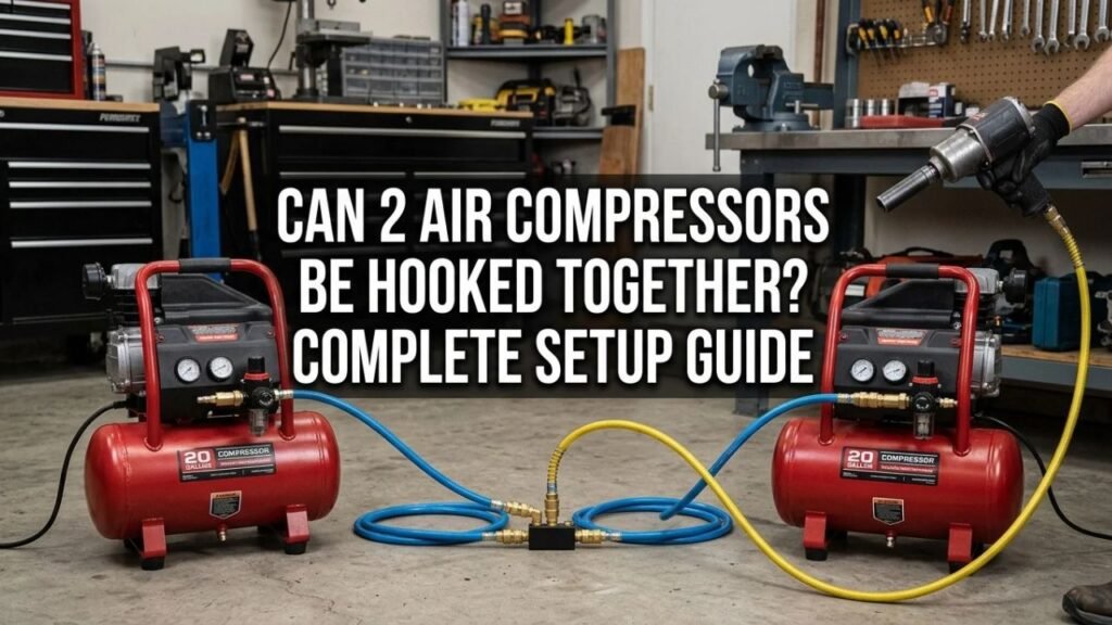
Yes, as long as the system is arranged so neither compressor can overpressure or backfeed the other.
Connect Them in Parallel
For ordinary shop use, both compressors should feed the same downstream air line.
A simplified layout is:
Compressor A → check valve → common manifold ← check valve ← Compressor B
The outlet from the manifold then supplies the regulator, hose, or shop piping.
This arrangement allows either compressor to contribute air when its pressure controls call for operation.
Quincy recommends check valves on the compressor discharge branches, a common connection, pressure controls, and suitable piping when networking two compressors.
Do Not Connect Them in Series
Series operation would mean the discharge from one ordinary shop compressor feeds the inlet of another.
That is not the right method for combining typical reciprocating garage compressors.
A compressor’s inlet and pump are designed for their specified intake conditions. Feeding already compressed air into a standard atmospheric inlet can exceed design limits and create excessive pressure, heat, or mechanical loading.
Purpose-built booster compressors are different because they are specifically engineered to accept pressurized inlet air.
Keep Every Receiver Within Its Pressure Rating
Suppose you have:
- Compressor A: 125 PSI maximum
- Compressor B: 175 PSI maximum
You cannot safely allow the shared system to rise to 175 PSI if the 125 PSI receiver remains directly connected to it.
The common system must stay within the pressure rating of its lowest-rated exposed component, or the system needs professionally designed pressure isolation.
Key Takeaway: Connect ordinary shop compressors in parallel through a common air line, isolate the branches against backflow, and never expose the lower-rated receiver to pressure above its rating.
What Happens When You Connect Two Air Compressors Together?
Three things can increase: airflow capacity, stored-air volume, and recovery capability.
Pressure does not double.
Available CFM Can Increase
If Compressor A delivers 5 SCFM at 90 PSI and Compressor B delivers 6 SCFM at 90 PSI, the pair may provide roughly 11 SCFM at that pressure under favorable conditions.
Real output can be lower because of:
- Hose restrictions
- Coupler restrictions
- Pressure drop
- Different control settings
- Pump performance
- Temperature
- Leakage
Quincy states that pairing compatible compressors can increase available air supply and support applications where one unit alone cannot provide enough airflow.
This is useful for tools such as DA sanders, die grinders, spray equipment, or other loads that can outrun a small compressor.
Tank Capacity Also Adds Together
If one compressor has a 20-gallon receiver and the second has a 30-gallon receiver, the connected system has about 50 gallons of combined storage available at the shared pressure.
That does not turn the pumps into larger pumps.
The extra storage mainly gives you:
- Longer bursts before pressure falls
- More reserve air
- Longer compressor recovery intervals in some use patterns
Once a continuous tool consumes more air than both compressors can produce, pressure will still fall eventually.
PSI Does Not Add
This point matters.
Connecting two 125 PSI compressors together gives you more air capacity at up to their allowed system pressure. It does not create 250 PSI.
Think of two water pumps feeding the same properly controlled header: combining flow does not simply double the operating pressure.
Key Takeaway: Connecting compressors can add their usable airflow and receiver storage, but it does not add their pressure ratings together.
Can You Connect Two Different-Size Air Compressors?
Yes, different sizes can share a system, but control behavior becomes more noticeable.
Different CFM Ratings Can Work
A 3-gallon portable compressor and a 20-gallon shop compressor can technically feed a common manifold if their pressures, fittings, hoses, and controls are compatible.
The larger compressor will probably carry more of the sustained workload.
For a more useful combination, both compressors should have enough output to contribute meaningfully to the intended tool demand.
Different Cut-In Pressures Change Which Compressor Runs First
Imagine:
- Compressor A starts at 105 PSI
- Compressor B starts at 90 PSI
As system pressure falls, Compressor A starts first.
If it can keep up with air demand, pressure may never fall to 90 PSI, so Compressor B may never run.
This can be useful if you intentionally want one compressor to act as the primary unit and the other as backup.
Matching Pressure Settings Shares Load More Closely
Quincy recommends synchronized pressure settings when the goal is to distribute work more evenly between connected compressors.
In a simple garage system, exact matching can also cause both motors to start near the same time.
That creates a large electrical starting load.
For that reason, deliberately staggered settings can sometimes be preferable when the system is designed as a lead-lag arrangement.
Industrial installations often use a master controller instead of relying only on overlapping pressure-switch bands. Kaeser notes that a master controller can start, load, unload, and stop multiple compressors to keep system pressure within a narrower operating range.
Key Takeaway: Different-size compressors can work together, but pressure-switch settings determine whether they share the workload, operate in stages, or leave one compressor doing most of the work.
How to Connect Two Air Compressors Together
For a basic two-compressor shop system, both units can retain their own tank, motor controls, pressure switch, unloader, and safety valve.
Step 1: Check Both Compressor Ratings
Before buying fittings, record each compressor’s:
- Maximum working pressure
- Cut-in pressure
- Cut-out pressure
- SCFM at your intended working PSI
- Outlet fitting size
- Electrical requirements
Base the shared system pressure on the lowest-rated component that will see full receiver pressure.
Step 2: Inspect Both Receivers
Do not connect a tank with:
- Severe rust
- Known pressure damage
- Bulges
- Leaking welded seams
- Missing or modified safety equipment
OSHA requires workplace receivers to be drained frequently enough to prevent excessive liquid accumulation and requires pressure gauges and spring-loaded safety valves.
Do not plug or defeat the factory relief valve.
Step 3: Use Pressure-Rated Hose or Piping
Use components designed for compressed-air service and rated above the intended system pressure.
Avoid improvised plumbing or hose connections whose pressure rating is unknown.
Size the common line generously enough to pass the combined airflow without creating unnecessary pressure drop.
Step 4: Install One-Way Check Valves
Put a suitable check valve in each compressor branch before the two flows join.
The valves should allow air to travel toward the common manifold and prevent air from flowing backward toward the other compressor.
Quincy specifically recommends one-way check valves to prevent backflow if one connected compressor is stopped or unavailable.
Some compressors already have an internal tank check valve, but that valve may serve a different part of the system. Do not assume it provides all the isolation required for a modified shared-air installation.
Step 5: Join the Branches at a Manifold or T-Fitting
Bring both compressor outlets into a pressure-rated T-fitting or manifold.
A manifold is convenient because it can provide:
- One inlet from each compressor
- Common pressure gauge
- Regulated tool outlets
- Additional shop-air branches
For larger systems, a properly sized header is better than a small hardware-store T that creates a major restriction.
Step 6: Set the Pressure Controls
There are two practical approaches.
For equal sharing, compatible compressors can use similar cut-in and cut-out pressure ranges.
For staged operation, set one compressor as the lead unit and let the second start only when pressure drops farther.
Do not raise a factory pressure switch above the compressor or receiver rating simply to make both machines synchronize.
Step 7: Check Electrical Capacity
Each compressor motor can draw a large startup current.
Two portable units should not automatically be plugged into the same household branch circuit.
If both try to start together, the combined surge may trip the breaker or overheat an undersized electrical circuit.
Follow each compressor’s circuit requirements. Hardwired or higher-horsepower installations should be checked by a qualified electrician.
Step 8: Test With No Tool Connected
Pressurize the system while watching both gauges.
Check for:
- Air leaks
- Reverse flow
- Unexpected pressure rise
- Relief-valve discharge
- One compressor continuously fighting the other
- Rapid motor cycling
Confirm that each compressor starts, stops, and unloads normally.
Step 9: Test Under Real Air Demand
Connect the intended tool and monitor system pressure.
If pressure drops badly even with both compressors running, the problem may be:
- Combined CFM still too low
- Restrictive hose
- Small couplers
- Undersized manifold
- Air leaks
Do not solve a flow shortage by raising receiver pressure beyond the system rating.
Key Takeaway: Check pressure ratings first, isolate both compressor branches with suitable one-way valves, join them at a rated manifold, preserve each compressor’s safety controls, and test both pressure behavior and electrical loading.
Do You Need Check Valves Between Two Air Compressors?
For a properly designed parallel connection, branch isolation is strongly recommended.
Check Valves Prevent Backflow
Without isolation, one compressor may push stored air toward the other unit.
That can affect:
- Tank pressure
- Unloader operation
- Startup
- Pressure controls
- Maintenance isolation
A one-way valve allows each compressor to feed the shared line without accepting reverse flow from the other branch.
Check Valves Do Not Replace Relief Valves
A check valve controls flow direction.
A relief valve protects a pressure vessel from excessive pressure.
They serve completely different jobs.
OSHA states that no valve may be placed between an air receiver and its required safety valve.
Never arrange a new check valve or shutoff valve in a way that isolates a receiver from its factory safety relief device.
Shutoff Valves Need Careful Placement
Isolation valves can make servicing easier, but the location matters.
Each tank still needs its pressure protection active regardless of the position of the shop piping valves.
Key Takeaway: Use check valves to stop one compressor from backfeeding the other, but never treat a check valve as a substitute for the receiver’s safety relief valve.
Should Both Air Compressors Have the Same Pressure Switch Setting?
They can, but they do not always need to.
Same Settings for Equal Sharing
If two closely matched compressors use the same cut-in and cut-out points, both tend to respond to the same pressure changes.
This can split operating hours more evenly.
Quincy’s two-compressor connection guidance recommends matching the pressure-switch settings when equal load sharing is desired.
Staggered Settings for Lead-Lag Operation
Suppose Compressor A operates from 105 to 135 PSI and Compressor B operates from 95 to 125 PSI.
During low demand, Compressor A may carry the system.
During higher demand, pressure falls far enough for Compressor B to join.
This staged strategy can reduce unnecessary operation of the second machine.
Large Systems Need Better Controls
With several compressors or variable-speed units, individual pressure switches can create wide pressure bands and poor loading patterns.
Atlas Copco notes that central control can balance running hours and choose which compressor should load as demand changes.
Key Takeaway: Matching pressure switches favors equal sharing, while staggered settings can create primary-and-assist operation; larger systems are better managed with coordinated controls.
Can Two Air Compressors Run One High-CFM Tool?
Yes, if their combined delivered airflow is high enough at the tool’s required pressure.
Imagine a pneumatic sander requires 10 SCFM at 90 PSI.
If:
- Compressor A supplies 6 SCFM at 90 PSI
- Compressor B supplies 5 SCFM at 90 PSI
the pair has enough rated flow on paper.
The tool may still perform poorly if the common hose, couplers, regulator, or manifold is too restrictive.
A small 1/4-inch hose setup can waste the benefit of pairing two compressors intended to supply a continuous high-flow tool.
For sustained use, leave some airflow margin rather than selecting compressors whose combined rating exactly equals the tool’s stated consumption.
Can You Connect Two Compressor Tanks Without Running Both Pumps?
Yes, a second approved receiver can add storage capacity, but that is a different goal from combining compressor output.
If only one pump runs, the system still has only that pump’s sustained CFM.
The extra receiver can provide a longer temporary burst before pressure drops, then the same compressor must refill a larger total volume.
The receiver needs:
- Suitable pressure rating
- Proper relief protection
- Pressure gauge where required
- Drain provision
- Pressure-rated piping
OSHA requires workplace receivers to have accessible drainage and pressure-relief equipment.
Do not repurpose an unknown tank or damaged vessel as an auxiliary air receiver.
Common Problems After Connecting Two Compressors
One Compressor Does All the Work
Its cut-in pressure may be higher than the second unit’s, or the second compressor may have a restrictive branch connection.
Check control settings before changing hardware.
Both Compressors Start at Once
Matching pressure settings can cause simultaneous motor starts.
Make sure the electrical service and branch circuits can support the startup demand.
A lead-lag pressure arrangement can separate start times.
The System Builds Pressure but the Tool Is Still Weak
Look for a flow restriction.
Common causes include a small regulator, narrow hose, undersized coupler, restrictive T-fitting, or clogged filter.
One Compressor Backfeeds the Other
Check the branch isolation valves.
A failed, missing, or incorrectly oriented check valve can allow reverse airflow.
One Safety Valve Opens
Stop the system.
A relief valve opening can indicate incorrect control settings, a pressure-switch problem, or exposure of one receiver to pressure above its intended range.
Do not plug the valve or substitute a higher-pressure relief valve as a shortcut.
Rapid Cycling Increases
Small pressure differentials or poor control coordination can cause repeated starts and stops.
Frequent motor starting can shorten equipment life.
A larger receiver or better sequencing may improve a properly engineered installation, but first verify that air demand and control settings are reasonable.
Key Takeaway: Uneven loading, simultaneous starts, restrictions, backflow, relief-valve opening, and rapid cycling usually point to control, sizing, or connection problems rather than a need for higher pressure.
Conclusion
For can 2 air compressors be hooked together, yes—two compatible compressors can operate in parallel and supply one common air system. The arrangement can increase available CFM, add stored-air capacity, and provide backup when one machine cannot meet peak demand.
The normal approach is to feed each compressor through suitable one-way isolation into a pressure-rated manifold or header. Keep each receiver’s original safety relief protection intact, and make sure the shared pressure never exceeds the rating of the lowest-rated exposed tank, hose, regulator, fitting, or accessory.
Pressure-switch settings decide how the workload is split. Closely matched settings can make two similar compressors share demand, while staggered settings can let one machine serve as the lead and bring the second online only during heavier use.
Finally, size the hoses and manifold for the combined CFM and check the electrical supply before operating both motors together. Connecting two undersized compressors can improve available airflow, but it cannot compensate for restrictive piping, an overloaded electrical circuit, or a tool whose continuous air demand remains greater than the combined compressor output.
FAQs About Connecting Two Air Compressors Together
Can I Connect Two Air Compressors Together?
Yes.
Two compatible compressors can feed a common air manifold in parallel. Proper branch isolation, pressure ratings, pressure controls, piping size, and electrical supply are required.
Will Connecting Two Air Compressors Double the CFM?
Their available airflow can be close to the sum of both compressors’ delivered CFM at the same pressure.
Real output can be reduced by piping losses, regulators, hoses, fittings, leakage, and differing compressor control behavior.
Will Connecting Two Air Compressors Double the PSI?
No.
Two compressors supplying a common line do not add their pressures together. System pressure remains governed by the compressor controls and the pressure limits of the connected equipment.
Can I Connect a 125 PSI Compressor to a 175 PSI Compressor?
Only if the shared system is controlled so the 125 PSI compressor and receiver are never exposed above their permitted pressure.
Running the common line at 175 PSI with a directly connected 125 PSI receiver would be unsafe.
Do Two Connected Compressors Need the Same Tank Size?
No.
Tank capacities can differ. Pressure compatibility, airflow, controls, and safe connection design matter more than matching receiver gallons.
Do I Need a Check Valve for Each Compressor?
A properly designed parallel setup should prevent reverse flow into either compressor.
Quincy recommends installing a check valve on each compressor discharge branch before the outputs are joined.
Can Two Small Compressors Run an Air Sander?
Yes, if their combined delivered SCFM at the required pressure exceeds the sander’s air consumption and the hoses, regulator, couplers, and manifold can pass that airflow.
Continuous pneumatic sanders can consume substantial air, so leave some capacity margin.
Can I Plug Both Compressors Into the Same Outlet?
Do not assume that you can.
Two compressor motors can produce a large combined running current and an even larger startup load. Follow each unit’s electrical requirements and use properly sized circuits rather than relying on a power strip or overloaded branch circuit.