
How to Combine Two Air Compressors Together and Run Them Safely
Two air compressors can be run together by connecting their air outlets to a common manifold or T-fitting through properly rated hoses and one-way check valves. Both compressors then feed the same air line, allowing their available airflow to combine while the check valves prevent one compressor from pushing air backward into the other.
Running two compressors in parallel can be useful when one unit cannot keep up with an air tool, spray equipment, or other high-CFM demand. It can also provide additional stored air and give a shop more flexibility without immediately replacing an existing compressor.
The safest arrangement leaves each compressor’s original pressure switch, safety valve, unloader, motor protection, and receiver tank intact. The compressors share only the compressed-air distribution side rather than being modified internally.
If you are learning how to combine two air compressors together, pay close attention to pressure ratings. The common hoses, fittings, manifold, regulator, and accessories must safely handle the highest pressure that can reach them.
For how to run two air compressors together, the compressors do not necessarily have to be identical. Matching units are easier to balance, but compressors of different sizes can share a system when their pressures, controls, check valves, airflow, and electrical requirements are managed correctly.
The U.S. Department of Energy has reported that compressed-air systems use roughly 90 billion kWh of electricity annually in the United States, with much of the input energy ultimately becoming heat. That makes proper control especially important when two compressors are operated instead of one.
Can You Connect Two Air Compressors Together?
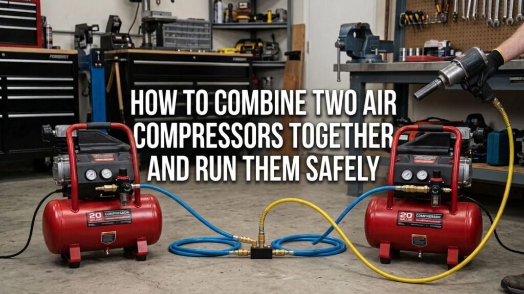
Yes. Multiple compressors commonly supply one shared compressed-air system.
Industrial plants routinely operate several compressors connected to a common header.
A smaller shop can use the same basic principle with two portable or stationary units.
Their Airflow Can Work Together
Suppose one compressor delivers 5 SCFM at 90 PSI and another delivers 6 SCFM at 90 PSI.
If both can feed the line freely at the same working pressure, their combined output may approach:
11 SCFM at 90 PSI
Actual airflow can be lower because of:
- Regulators
- Hose restrictions
- Couplers
- Check valves
- Pressure differences
- Temperature
- Compressor condition
Pressure Does Not Add Together
Connecting two compressors does not add their PSI ratings.
A 125 PSI compressor connected to another 125 PSI compressor does not create 250 PSI.
They both supply the same common air system.
Tank Capacity Is Not Pump Capacity
Connecting two receivers gives the system more stored compressed air, but tank size does not create additional CFM.
Sustained tool operation still depends on the combined output of the compressor pumps.
Key Takeaway: Two compressors can share one air system and combine their airflow, but pressure does not add together and tank volume does not replace adequate pump CFM.
Why Run Two Air Compressors Together?
There are several reasons to operate compressors in parallel.
More Available CFM
This is the most common reason.
High-demand pneumatic equipment may consume more air than one compressor can continuously supply.
Examples include:
- Air sanders
- Die grinders
- Spray guns
- Sandblasting equipment
- Air drills
- Continuous blow guns
Adding a second compressor can increase the available airflow.
More Stored Air
Two receiver tanks provide a larger reserve.
This can reduce pressure drop during short bursts of demand.
Use Equipment You Already Own
If you already own two smaller compressors, connecting them may be less expensive than immediately purchasing one larger unit.
Backup Capability
One compressor can sometimes remain usable if the other needs maintenance.
This is not full redundancy unless either unit can handle the required load by itself.
Reduced Workload on One Compressor
If the system is controlled properly, two compressors can share demand rather than forcing one machine to run continuously.
Key Takeaway: Combining compressors can provide more airflow, additional storage, workload sharing, and limited backup capacity.
What Do You Need to Connect Two Air Compressors?
A basic parallel arrangement does not require major modifications.
Air Hose or Rated Piping
Each compressor needs a line leading toward the common connection.
Use air hose or piping rated above the maximum system pressure.
Hose diameter also matters.
An undersized hose can restrict airflow even if both compressors produce plenty of CFM.
T-Fitting or Air Manifold
The two supply lines need a common connection.
You can use:
- Rated T-fitting
- Multi-port air manifold
- Properly sized compressed-air header
The third port becomes the combined outlet.
Check Valves
Install a one-way valve in each compressor branch.
The valve should allow air to move:
Compressor → common manifold
but prevent flow in the opposite direction.
Common Output Regulator
For many setups, a regulator downstream of the combined manifold provides the cleanest way to control tool pressure.
For example:
- Compressors supply manifold at higher pressure.
- Final regulator is set to 90 PSI.
- Tool receives regulated 90 PSI air.
Pressure Gauge
A gauge on the common header lets you see the actual system pressure.
Shutoff Valves
Isolation valves make servicing easier.
A valve in each compressor branch lets one unit be disconnected without dismantling the entire system.
Proper Fittings
All:
- Nipples
- Couplers
- Tees
- Valves
- Regulators
must have suitable pressure and flow ratings.
Key Takeaway: A practical two-compressor setup uses rated air lines, a common manifold, check valves, isolation valves, a pressure gauge, and usually a downstream regulator.
Why Check Valves Are Important
One-way check valves are one of the most useful components in a parallel compressor system.
They Prevent Backflow
Suppose Compressor A is at 140 PSI and Compressor B is at 110 PSI.
Without branch isolation, air from A may flow toward B rather than entirely toward the tool.
A check valve prevents this reverse flow.
They Isolate an Idle Compressor
If one compressor is turned off, the operating unit should not continually pressurize its outlet plumbing in the wrong direction.
They Reduce Compressor Interaction
Different compressor pressure switches may operate at different points.
Check valves help keep the two pump systems from interfering with each other.
Install Them in the Correct Direction
A check valve normally has an arrow showing flow direction.
It should point toward:
Common manifold
not back toward the compressor.
Key Takeaway: Put a check valve in each compressor supply branch so air can flow toward the common system without being pushed backward through the other compressor.
How to Combine Two Air Compressors Together Step by Step
The following arrangement keeps the original compressor systems largely unchanged.
Step 1: Compare Both Compressor Ratings
Check the nameplates or manuals for:
- Maximum pressure
- Cut-in pressure
- Cut-out pressure
- SCFM at 90 PSI
- Tank capacity
- Electrical requirements
Pay special attention to the lower maximum-pressure rating.
The shared system should never expose the lower-rated compressor or components to excessive pressure.
Step 2: Turn Both Compressors Off
Disconnect electrical power while assembling the air connections.
Release pressure from lines you will be opening.
Step 3: Keep the Original Safety Components
Do not remove or bypass:
- Safety relief valves
- Tank check valves
- Pressure switches
- Unloader valves
- Motor overloads
Each compressor should continue protecting itself independently.
Step 4: Connect the First Compressor to a Check Valve
Run a suitable air hose or pipe from Compressor A’s approved outlet.
Install a check valve with its flow arrow pointing away from the compressor.
Step 5: Repeat for the Second Compressor
Connect Compressor B to its own check valve.
Do not depend on a single check valve after the T-fitting to prevent compressor-to-compressor backflow.
Each branch should have its own isolation.
Step 6: Connect Both Branches to a Manifold
Join the two lines using a properly rated manifold or T-fitting.
The basic arrangement looks like this:
Compressor A → Check Valve →
Manifold → Regulator → Tool
Compressor B → Check Valve →
Step 7: Add Isolation Valves
An isolation valve on each branch makes future maintenance easier.
You can shut off one compressor while leaving the other connected to the system.
Step 8: Install a Common Pressure Gauge
Place a gauge where it can show the shared header pressure.
This makes it easier to understand when:
- One compressor starts
- The second starts
- Pressure falls under load
Step 9: Add a Final Regulator
A regulator after the manifold can control pressure delivered to your tool.
For example, if both compressor systems operate around 120–150 PSI but your tool requires 90 PSI, set the downstream regulator to the required tool pressure.
Step 10: Pressurize Slowly
Close the tool valve or stop tool demand.
Start one compressor first.
Check:
- Connections
- Check-valve direction
- Leaks
- Gauge readings
Then start the second compressor.
Step 11: Test Under Load
Operate the intended air tool and watch system pressure.
The pressure should remain within an acceptable range when both compressors are running.
Key Takeaway: Connect each compressor through its own check valve into a shared manifold, regulate the combined output, then test for leaks and pressure stability before heavy use.
How to Run Two Air Compressors Together
Connecting the hoses is only one part of the job.
The compressors also need sensible operating controls.
Both Compressors Can Start Independently
The easiest arrangement is to leave both factory pressure switches intact.
Each compressor starts when its own tank pressure reaches its normal cut-in point.
Different Settings Can Make One Compressor Work More
Imagine:
Compressor A:
- Starts at 105 PSI
- Stops at 135 PSI
Compressor B:
- Starts at 90 PSI
- Stops at 120 PSI
Compressor A may handle much of the normal demand before pressure ever drops enough for Compressor B to start.
This can be useful if you intentionally want:
- One lead compressor
- One lag compressor
It is less desirable if you want equal runtime.
Matching Pressure Bands Gives More Equal Operation
Compressors with similar pressure-switch settings tend to work together more evenly.
Do not arbitrarily adjust factory pressure switches beyond their approved settings.
An incorrect adjustment can exceed:
- Tank rating
- Pump rating
- Motor load
- Safety design
Lead-Lag Operation Can Be Useful
Rather than forcing both compressors to start every time, you can allow one to handle ordinary demand.
The second starts only if pressure falls farther.
This reduces unnecessary starts and runtime.
Key Takeaway: Factory pressure switches can operate independently, while their cut-in settings determine which compressor runs first and when the second joins the system.
Can You Connect Two Different-Size Air Compressors?
Yes, they do not have to be identical.
Match the Working Pressure
The common system pressure must remain safe for both compressors.
Suppose:
Compressor A:
- 150 PSI maximum
Compressor B:
- 125 PSI maximum
Do not expose the 125 PSI machine to 150 PSI through the connecting system.
Different CFM Ratings Are Acceptable
A 4 CFM compressor can work beside an 8 CFM compressor.
Together they may provide roughly 12 CFM at a common rated pressure, subject to restrictions and control behavior.
Different Tank Sizes Are Also Acceptable
You could connect:
- 6-gallon compressor
- 20-gallon compressor
The tank sizes do not need to match.
Control Behavior May Be Uneven
The larger compressor may:
- Run longer
- Recover faster
- Carry more load
That is not necessarily a problem.
It simply means the system will not divide the work equally.
Key Takeaway: Different-size compressors can operate together as long as pressure compatibility, check valves, airflow restrictions, and control behavior are properly addressed.
Can You Connect a 125 PSI Compressor to a 150 PSI Compressor?
It can be done only if the lower-rated equipment is protected from the higher pressure.
Use the Lower Pressure as the Safe Limit
If one compressor or receiver is limited to 125 PSI, do not allow 150 PSI from the other machine to backfeed into it.
Check Valves Help
Separate check valves stop reverse flow between branches.
Regulation May Be Needed
The 150 PSI machine may need its output controlled before it joins a system that cannot safely accept that pressure.
All Shared Components Need Adequate Ratings
Check:
- Manifold
- Hoses
- Couplers
- Regulators
- Filters
- Moisture separators
Never assume a fitting is suitable just because it screws into the port.
Should Both Compressors Use the Same PSI Setting?
Not always.
It depends on your goal.
Same or Similar Settings
Use similar operating ranges when you want both machines to share demand more evenly.
Staggered Settings
Use different cut-in points when you want lead-lag behavior.
For example:
- Compressor A starts first.
- Compressor B starts only during high demand.
Avoid Random Pressure-Switch Adjustment
Many switches have adjustment screws, but that does not mean every setting is safe.
Changing cut-out pressure can increase:
- Motor load
- Pump temperature
- Tank stress
Follow the manufacturer’s approved pressure range.
Key Takeaway: Similar pressure settings encourage workload sharing, while staggered settings can create lead-lag operation; stay within each compressor’s approved pressure limits.
Can You Connect the Compressor Tanks Directly Together?
Technically, receiver tanks can be connected into a shared storage system, but this needs more care than connecting their normal outlets.
Do Not Use the Drain Port Casually
The drain opening is intended primarily for condensate removal.
Using it as a permanent main airflow connection can interfere with drainage and may place fittings where they are exposed to damage.
Use Approved Tank Ports
If a direct receiver connection is planned, use ports approved for compressed-air service.
Keep Safety Valves Installed
Every receiver needs proper overpressure protection.
Never plug a relief-valve opening to create an extra connection.
Tank-to-Tank Piping Becomes Part of the Pressure System
The connecting pipe, valves, unions, and fittings need suitable:
- Pressure ratings
- Material
- Diameter
- Mechanical protection
For permanent shop installations, professional system design is preferable to improvised tank modifications.
Key Takeaway: Directly joining receiver tanks is possible in properly engineered systems, but using the compressors’ normal approved air outlets is usually simpler for a small-shop setup.
How Much CFM Do Two Compressors Produce Together?
In a well-designed parallel arrangement, usable airflow can approach the sum of both compressor outputs at the same pressure.
Example
Compressor A:
- 5.0 SCFM at 90 PSI
Compressor B:
- 6.5 SCFM at 90 PSI
Theoretical combined output:
11.5 SCFM at 90 PSI
Restrictions Reduce Delivered Air
Real-world output can be lower because of:
- 1/4-inch fittings
- Narrow hoses
- Restrictive quick couplers
- Small regulators
- Dirty filters
- Long hose runs
Compare at the Same Pressure
Do not add:
- One compressor’s CFM at 40 PSI
to:
- Another compressor’s CFM at 90 PSI
Use ratings at the pressure required by the tool.
Key Takeaway: Combined CFM can approach the sum of both compressors at the same operating pressure, but restrictive plumbing can prevent the tool from receiving that full airflow.
Hose Size Matters When Combining Compressors
Adding a second compressor will not help much if the combined outlet is badly restricted.
Small Hose Creates Pressure Drop
High-flow tools may perform poorly through long, narrow hoses.
For greater airflow, a larger inside diameter is often preferable.
Fittings Can Be the Bottleneck
A large hose connected through several tiny couplers still has a restriction.
Look at the entire path:
- Compressor outlet
- Check valve
- Tee
- Regulator
- Filter
- Coupler
- Hose
- Tool fitting
Keep the Manifold Properly Sized
A tiny manifold can choke two large compressors.
Match the distribution hardware to the airflow you expect to use.
Can Two Compressors Power One High-CFM Air Tool?
Yes, if their combined delivered airflow meets the tool’s demand.
Check the Tool’s CFM Rating
Suppose an air sander requires:
10 CFM at 90 PSI
One compressor produces:
5.5 SCFM at 90 PSI
The second produces:
6 SCFM at 90 PSI
Together, they may provide enough air if the plumbing is not restrictive and both compressors can sustain their rated output.
Duty Cycle Still Matters
A small portable compressor may not be rated for continuous operation.
Even if two units have enough combined CFM on paper, sustained high-demand use can keep both running continuously.
Check each compressor’s duty-cycle limitations.
Tank Size Only Buys Time
Large receivers can support short bursts.
They do not correct a continuous airflow shortage.
Key Takeaway: Two compressors can run one high-CFM tool when their combined sustained output at the required PSI exceeds the tool’s air consumption.
Electrical Safety When Running Two Air Compressors
The electrical side deserves just as much attention as the air plumbing.
Compressors Draw High Starting Current
Electric motors draw considerably more current during startup than during normal running.
Two compressors starting together can create a large momentary electrical load.
Separate Circuits May Be Needed
Do not assume two compressors can safely run from:
- One household receptacle
- One extension cord
- One power strip
Follow each compressor’s electrical requirements.
Avoid Undersized Extension Cords
Voltage drop can cause:
- Hard starting
- Motor heating
- Breaker trips
- Reduced motor life
Plug compressors directly into suitable circuits when possible.
Do Not Upsize a Breaker to Stop Tripping
A larger breaker can leave undersized wiring inadequately protected.
Repeated trips should lead to inspection of:
- Circuit capacity
- Voltage
- Motor condition
- Compressor load
- Extension cords
For permanent or high-power installations, use a qualified electrician.
Key Takeaway: Two compressors can place a heavy load on the electrical system, especially during startup, so use properly sized circuits rather than sharing an overloaded outlet.
Do You Need a Separate Regulator for Each Compressor?
It depends on the plumbing arrangement.
One Common Final Regulator Is Convenient
A common arrangement is:
Compressor → Check Valve →
Manifold → Final Regulator → Tool
Compressor → Check Valve →
This gives you one tool-pressure adjustment.
Compressor Regulators Can Still Remain Installed
Portable units often have built-in outlet regulators.
If connecting through those outlets, set them high enough to supply the common system without excessive restriction while remaining within all equipment ratings.
Avoid Regulators Fighting Each Other
If one outlet regulator is set to 100 PSI and another is set to 80 PSI, the higher-pressure compressor may supply most of the air until system pressure falls.
For balanced operation, pressure settings need to make sense together.
Should Both Compressors Start at the Same Time?
Usually, they do not need to.
Simultaneous Starting Creates High Electrical Demand
Starting two motors at once can increase:
- Voltage drop
- Breaker loading
- Generator load
Staggered Starting Is Often Better
Lead-lag operation allows one compressor to start first.
The second joins only when demand requires it.
Industrial Systems Use Sequencing
Larger multiple-compressor installations often use controllers to:
- Rotate lead duty
- Balance runtime
- Add capacity as pressure falls
- Avoid unnecessary operation
A two-compressor home-shop setup can use a much simpler version of the same concept through properly chosen pressure settings.
Key Takeaway: Staggered compressor operation often reduces electrical stress and unnecessary runtime compared with making both machines start for every pressure drop.
Common Problems When Running Two Compressors Together
A system may connect successfully and still perform poorly.
One Compressor Does All the Work
Cause:
- Different pressure settings
- Restrictive second branch
- Faulty check valve
Check the cut-in pressures and airflow path.
Air Flows Back Into One Compressor
Cause:
- Missing check valve
- Failed check valve
- Incorrect valve direction
Install or replace the branch check valve.
Tool Pressure Still Drops
Possible causes include:
- Combined CFM still too low
- Hose too small
- Regulator restriction
- Undersized couplers
- Air leaks
Both Compressors Run Continuously
Your air demand may exceed their combined sustainable output.
Check:
- Tool CFM
- Compressor SCFM
- System leaks
- Duty cycles
Breaker Trips
Possible causes include:
- Both motors on one circuit
- Simultaneous starting
- Undersized extension cord
- Low supply voltage
- Motor fault
Do not solve this by installing a larger breaker without verifying the circuit.
Key Takeaway: Unequal runtime, backflow, pressure loss, continuous operation, and breaker trips usually point to control, plumbing, capacity, or electrical problems rather than the basic idea of using two compressors.
Mistakes to Avoid When Combining Two Air Compressors
A few shortcuts can turn a simple project into an unsafe system.
Connecting Without Check Valves
This can let the higher-pressure compressor feed backward toward the other unit.
Exceeding the Lower Pressure Rating
The safest pressure limit is determined by the lowest-rated component exposed to the shared pressure.
Using Tiny Air Fittings
Restricted plumbing can erase much of the airflow gained by adding the second compressor.
Modifying Safety Valves
Never remove, plug, or defeat a receiver’s relief valve.
Bypassing Pressure Switches
Each compressor should retain automatic overpressure control.
Running Both Motors From an Inadequate Circuit
Two compressors may need separate electrical circuits.
Using PVC Water Pipe for Shop Air
Ordinary PVC or CPVC water piping is not a suitable choice for exposed compressed-air distribution because failure can create dangerous fragments.
Use piping specifically appropriate for compressed-air service.
Ignoring Condensate
Both receiver tanks still need regular draining.
Adding another tank means another place for moisture to collect.
Key Takeaway: Preserve every compressor’s safety controls, use pressure-rated components, prevent backflow, provide enough airflow capacity, and supply each motor with adequate electrical power.
Is Running Two Compressors Better Than Buying One Bigger Compressor?
It depends on how often you need the extra air.
Two Compressors Make Sense When
- You already own both units.
- High air demand is occasional.
- Portability matters.
- You want limited backup capacity.
- Buying a larger compressor is not currently practical.
One Larger Compressor May Be Better When
- High CFM is needed every day.
- Both small units run continuously.
- Noise from two machines is excessive.
- Electrical setup becomes complicated.
- Maintenance on two machines is inconvenient.
Compare Sustained CFM
A single larger compressor designed for continuous high-flow use may outperform two small portable compressors even if their advertised numbers appear similar.
Consider:
- Duty cycle
- SCFM
- Motor size
- Cooling
- Tank capacity
- Noise
- Electrical supply
Conclusion
For how to combine two air compressors together, the safest general approach is to connect each compressor’s approved air outlet through its own check valve, join both lines at a pressure-rated manifold, and control the tool pressure with a common downstream regulator.
For how to run two air compressors together, leave the original pressure switches, safety valves, tank check valves, unloaders, and motor protection intact. The compressors can operate independently, with similar pressure settings for workload sharing or staggered settings for lead-lag operation.
The combined CFM can approach the sum of both compressors when measured at the same pressure, but small hoses, couplers, regulators, and fittings can restrict the result. Make the shared air path large enough for the required flow.
Check electrical capacity before turning both machines on. Two compressor motors can create significant startup current, and running them from one undersized household circuit or extension cord can cause voltage drop, overheating, or breaker trips.
When the setup becomes permanent, high horsepower, or business-critical, a properly engineered common header and compressor-control system is preferable to an improvised connection.
FAQs About Running Two Air Compressors Together
Can you hook two air compressors together to get more CFM?
Yes. If both compressors supply the same common pressure, their airflow can combine. A 5 SCFM compressor and a 6 SCFM compressor may provide close to 11 SCFM at the same rated PSI, minus system restrictions.
Will connecting two air compressors double the PSI?
No. Compressor pressure does not add. Two 125 PSI compressors connected together still operate within approximately the same system pressure range; their main benefit is greater airflow and storage.
Do I need check valves when connecting two air compressors?
Yes, separate branch check valves are strongly recommended. They prevent a higher-pressure compressor from pushing air backward into the other compressor.
Can I connect two different-size air compressors together?
Yes. They can have different CFM ratings and tank sizes. Their pressure ratings and controls must remain compatible with the shared system.
Can I connect a 150 PSI compressor to a 125 PSI compressor?
Only if the lower-rated compressor and components are protected from pressure above their ratings. Check valves and suitable regulation may be required.
Do both air compressors need the same pressure-switch settings?
No. Similar settings encourage workload sharing, while staggered cut-in pressures allow one compressor to act as the lead and the second as a backup or lag unit.
Can I run two air compressors from one electrical outlet?
Do not assume you can. Compressor motors draw substantial current, especially during startup. Each machine may require its own properly rated electrical circuit.
Is it better to run two small compressors or one large compressor?
Two small compressors can work well for occasional extra demand or when you already own them. A larger single compressor is often a cleaner solution for frequent, continuous high-CFM use.