
How to Plumb a Gas Powered Air Compressor: Setup and Diagram
A typical gas-engine reciprocating compressor is plumbed from the pump discharge to a receiver-tank check valve, with a pilot/unloader system controlling pressure and engine speed. The tank also needs a pressure gauge, safety relief valve, drain, and an outlet that feeds a regulator or shop-air system through pressure-rated tubing or hose.
Gas-powered compressors differ from many electric units because the gasoline engine commonly keeps running after maximum tank pressure is reached. A pilot unloader valve unloads the compressor pump and may move the engine to idle until tank pressure falls enough to resume pumping.
For how to plumb a gas powered air compressor, it helps to separate the system into three sections: the hot discharge side between pump and tank, the pressure-control and safety components on the receiver, and the regulated air outlet used by your tools.
Receiver safety cannot be treated like ordinary plumbing. For covered U.S. workplace air receivers, OSHA requires a pressure gauge and spring-loaded safety valve capacity sufficient to prevent pressure from exceeding the receiver’s maximum allowable working pressure by more than 10%. OSHA also prohibits installing a valve between the receiver and its safety valve.
Gasoline-engine exhaust adds another hazard. Operate the compressor outdoors in a clean, ventilated location and keep engine exhaust away from doors, windows, and occupied areas. ROLAIR’s gas-compressor instructions specifically state not to operate the compressor in an enclosed area.
The exact connections vary among compressor manufacturers, so factory diagrams take priority. The layout below shows how a common engine-driven reciprocating compressor with an air receiver is arranged.
Basic Gas Powered Air Compressor Plumbing Diagram
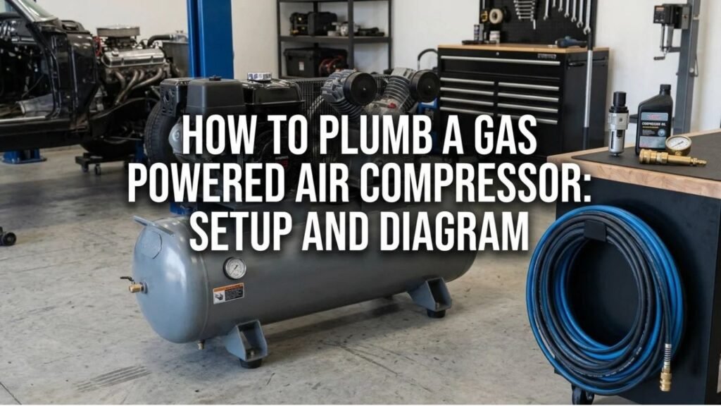
A common layout looks like this:
Compressor Pump → High-Temperature Discharge Line → Tank Check Valve → Air Receiver Tank → Outlet Valve → Filter/Water Separator → Regulator → Air Hose or Shop Piping
The pressure-control system typically connects to the receiver separately:
Receiver Tank → Pilot/Unloader Valve → Pump Unloader and/or Engine Throttle Control
The receiver also needs separate connections for:
- Pressure gauge
- Safety relief valve
- Drain valve
- Pilot/unloader valve
- Air outlet
Pump Discharge Line
The discharge line carries freshly compressed air from the pump to the receiver.
This air can be extremely hot.
Use tubing or hose rated for:
- Compressed air
- Maximum system pressure
- Compressor discharge temperature
- Vibration
Common factory arrangements use copper tubing or high-temperature braided flexible hose.
Do not replace a factory hot discharge tube with ordinary shop air hose unless that hose is specifically rated for the temperature and pressure.
Tank Check Valve
Install the tank check valve where the pump discharge enters the receiver.
It allows air to travel into the tank while preventing stored air from returning toward the compressor.
Quincy describes the normal check-valve location as the point where the compressor discharge enters the receiver.
The check valve is also important to unloading and easy starting.
Receiver Tank
The receiver stores compressed air and smooths pressure fluctuations.
Use a pressure-rated receiver intended for compressed air.
Do not build a receiver from:
- Propane cylinders
- Water tanks
- Unrated pipe
- Old corroded tanks
- Welded homemade containers
For applicable U.S. workplaces, OSHA requires new covered air receivers to meet the referenced ASME pressure-vessel requirements.
Pilot/Unloader Valve
The pilot unloader controls the operating cycle on many gasoline-powered compressors.
ROLAIR describes this valve as commonly used on gas-powered compressors. At the upper pressure setting, it unloads the compressor and can activate engine idle control.
Regulated Outlet
Air leaving the tank can be routed through:
- Shutoff valve
- Moisture separator/filter
- Regulator
- Lubricator if the tool requires one
- Quick coupler or shop piping
Do not put the regulator in the hot pump-discharge line unless the component was specifically designed for that location.
Key Takeaway: The basic flow is pump → hot discharge line → tank check valve → receiver → regulated outlet. The pilot/unloader, safety valve, gauge, and drain connect to the receiver as separate control and safety components.
What Parts Do You Need to Plumb a Gas Powered Air Compressor?
A bare compressor and engine need more than a hose and a tank.
Pressure-Rated Air Receiver
Choose a receiver with a maximum allowable working pressure above the compressor’s factory operating pressure.
The tank should have appropriate ports for:
- Pump inlet
- Outlet
- Gauge
- Relief valve
- Drain
- Control valve
Do not alter the tank by drilling or welding additional ports unless the manufacturer explicitly approves the modification.
Tank Check Valve
Choose a check valve with:
- Correct NPT size
- Adequate pressure rating
- Adequate temperature rating
- Flow capacity matching the compressor
Some valves also have a small side port for an unloader connection.
Pilot Unloader Valve
Gas-powered reciprocating compressors commonly use a pilot valve instead of repeatedly shutting the engine off.
Select the exact valve specified for the compressor system whenever possible.
Factory unload and reload settings should match:
- Receiver rating
- Compressor pump rating
- Engine-control system
Do not raise pilot pressure simply to store more air.
Pressure Gauge
Install a gauge with a pressure range suitable for the receiver.
It should be easy to see while operating the compressor.
Safety Relief Valve
Use a properly sized pressure-relief valve rated for compressed-air service.
Its set pressure must match the system design and receiver specifications.
Never:
- Plug the safety valve port
- Install a shutoff valve ahead of it
- Wire it closed
- Adjust it above the tank rating
Tank Drain
Install the drain at the receiver’s low point or use the receiver’s factory drain connection.
OSHA requires covered workplace receivers to have a method for removing accumulated oil and water and calls for draining frequently enough to prevent excessive liquid accumulation.
Outlet Ball Valve
A full-flow outlet valve allows the downstream air system to be isolated.
It belongs on the usable-air outlet, not between the tank and safety relief valve.
Filter and Water Separator
Compressed air contains moisture.
A separator downstream of the receiver can remove liquid water before it reaches:
- Air tools
- Spray equipment
- Regulators
- Distribution lines
For very dry applications, you may also need an air dryer.
Pressure Regulator
The regulator reduces receiver pressure to whatever the pneumatic tool requires.
For example, a compressor may store air at 125–150 PSI while a tool operates around 90 PSI.
Use the tool manufacturer’s pressure specification.
Key Takeaway: A complete installation normally needs a rated receiver, check valve, pilot unloader, pressure gauge, relief valve, drain, outlet valve, separator, and regulator.
How to Plumb the Pump to the Air Tank
The pump-to-tank side carries the hottest air in the system.
It needs different materials from the cooler downstream piping.
Step 1: Identify the Compressor Discharge Port
Find the discharge fitting on the compressor head.
Do not confuse it with:
- Intake port
- Crankcase vent
- Head-unloader connection
- Interstage line on a two-stage pump
Use the manufacturer’s pump diagram when connections are not obvious.
Step 2: Match the Discharge-Line Diameter
Do not reduce the pump outlet unnecessarily.
A discharge line that is too small creates:
- Pressure drop
- Extra heat
- Higher pump load
- Reduced airflow
A good starting rule is to keep the discharge connection at least as large as the compressor manufacturer’s outlet size unless the factory diagram specifies something different.
Step 3: Use a Heat-Rated Flexible Section
Gas-powered compressors vibrate.
A short braided metal hose or another manufacturer-approved flexible connection can prevent vibration from being transferred directly into rigid piping.
Ingersoll Rand compressor installation kits use braided hose and vibration-isolation components for this reason.
Keep flexible hose away from:
- Muffler
- Belt
- Flywheel
- Engine cylinder
- Sharp edges
Step 4: Connect the Line to the Tank Check Valve
The check valve belongs at or very near the tank inlet.
Check the flow direction before installation.
Air should flow:
Pump → Receiver
It should not flow:
Receiver → Pump
Step 5: Support the Line
Do not let a heavy pipe hang from the compressor head.
Use brackets or routing that keeps mechanical load off the pump fitting.
Leave room for vibration and thermal expansion.
Step 6: Check for Leaks
After pressurizing the system, check threaded fittings with an approved leak-detection solution.
Bubbles indicate leakage.
Depressurize the system before tightening or replacing fittings.
Key Takeaway: Keep the pump discharge unrestricted, heat-rated, vibration-resistant, properly supported, and connected through a correctly oriented tank check valve.
How to Plumb the Pilot Unloader on a Gas Air Compressor
This is the part that often causes confusion.
A gasoline engine cannot be controlled exactly like a normal electric compressor motor.
What the Pilot Valve Does
During normal pumping, the pilot valve allows the pump to load and fill the tank.
When tank pressure reaches the upper setting, the pilot valve changes state.
Depending on the compressor design, it may:
- Vent or unload the compressor pump
- Operate head unloaders
- Move the gasoline engine throttle to idle
- Perform more than one of these functions
When tank pressure falls to the reload setting, the pump loads again and the engine returns to operating speed.
Why Gas Compressors Use Unloading
Without an unloading system, the compressor would continue trying to pump into a full receiver.
That would cause pressure to keep increasing until another protection device opened.
The pilot valve maintains the normal operating pressure range while allowing the engine to keep running.
Where the Pilot Valve Senses Pressure
The pilot valve usually connects directly to receiver pressure through a tank manifold or receiver port.
It must sense true tank pressure.
Do not place a regulator between the receiver and the pilot-pressure connection.
Where the Small Unloader Line Goes
The exact layout varies.
On some compressors, a small line connects between:
- Tank check valve
- Pilot or unloader valve
Other designs use pneumatic lines to head unloaders.
ROLAIR replacement instructions show 1/4-inch unloader tubing connected into a check-valve side port on applicable systems.
Follow the compressor’s factory diagram rather than copying another machine’s tubing layout.
Do Not Randomly Adjust the Pilot Valve
Changing the upper pressure setting can exceed the ratings of:
- Tank
- Pump
- Hoses
- Fittings
- Tools
Many manufacturers set pilot pressure at the factory.
Leave pressure settings unchanged unless the service procedure specifically calls for adjustment.
Key Takeaway: The pilot unloader senses receiver pressure and unloads the pump at the upper setting, often idling the gas engine at the same time. Its tubing arrangement must match the compressor’s original design.
How to Plumb the Air Tank Outlet
The tank outlet supplies usable compressed air.
It should be arranged for good airflow and easy service.
Install a Full-Flow Shutoff Valve
Place a pressure-rated ball valve at the receiver outlet.
This allows you to isolate downstream piping.
Do not confuse this outlet valve with the safety relief connection.
Add a Flexible Connector
If the compressor is mounted on a truck, trailer, or vibrating frame, use a suitable flexible hose before rigid shop or vehicle piping.
The hose must be rated for the system’s maximum:
- Pressure
- Temperature
- Airflow
Install a Moisture Separator
Place the separator downstream where the air has had some opportunity to cool.
Cooler air releases condensed moisture more readily than extremely hot compressor discharge air.
Install the Regulator
Place the regulator after primary water separation.
The layout can look like:
Tank → Ball Valve → Water Separator → Regulator → Quick Coupler
For applications needing very clean air:
Tank → Separator → Dryer → Fine Filter → Regulator → Tool
Add a Lubricator Only When Needed
Some pneumatic tools benefit from airline lubrication.
Others must remain oil-free, especially:
- Paint spray systems
- Breathing-air systems
- Certain instruments
Do not install one common lubricator upstream of equipment that must remain oil-free.
Key Takeaway: Plumb the receiver outlet through a shutoff valve, moisture control, and regulator before sending air to tools or the distribution system.
What Pipe Should You Use for a Gas Air Compressor?
Pipe selection depends on pressure, temperature, location, and local code.
Pressure-Rated Aluminum Air Pipe
Purpose-built aluminum compressed-air systems are:
- Corrosion resistant
- Lightweight
- Easy to modify
- Smooth internally
They are common for permanent shop systems.
Copper
Copper can work well when:
- Tube type is suitable
- Joints are pressure rated
- Installation complies with applicable code
It resists internal rust and provides smooth airflow.
Steel or Stainless Steel
Properly rated steel piping can handle compressed air.
Its disadvantages can include:
- Weight
- Installation labor
- Internal corrosion in some materials
Pressure-Rated Flexible Hose
Use hose specifically rated for compressed air.
Check both:
- Working pressure
- Temperature rating
The discharge side near the pump needs a much higher temperature rating than an ordinary tool hose.
Do Not Use Ordinary PVC Water Pipe
Ordinary PVC and CPVC water pipe should not be treated as general compressed-air piping.
Brittle failure can throw hard fragments when pipe ruptures under compressed-gas pressure.
Quincy recommends compressed-air-appropriate materials such as aluminum, copper, or other rated systems and cautions against common PVC/CPVC installations.
Key Takeaway: Use pipe, tubing, hose, and fittings specifically rated for compressed air at the pressure and temperature they will experience. Ordinary water-plumbing PVC is a poor choice for exposed compressed-air service.
What Size Pipe Should You Use?
Pipe size should be chosen from compressor CFM, run length, allowable pressure drop, and fitting count.
Tank size alone does not determine pipe diameter.
Small Portable Gas Compressors
A small engine-driven compressor may use:
- 3/8-inch outlet
- 1/2-inch outlet
A short hose serving nailers or inflation equipment can often match the factory outlet size.
Higher-CFM Gas Compressors
Larger units may use:
- 3/4-inch
- 1-inch
- Larger piping
Reducing a high-CFM compressor to 1/4-inch fittings can waste much of its output through pressure drop.
Long Runs Need Larger Pipe
Long piping creates friction.
So do:
- Small quick couplers
- Elbows
- Filters
- Regulators
- Undersized hoses
Upsizing the main line can reduce pressure loss.
Branch drops can then be smaller based on tool demand.
How to Add an Auxiliary Tank to a Gas Powered Compressor
An additional receiver can increase stored-air capacity.
It does not increase the pump’s CFM.
Use a Rated Air Receiver
The second tank should be designed and rated for compressed air.
Never use an improvised tank.
Connect the Tanks With Adequate Flow Capacity
A typical arrangement is:
Compressor Receiver → Isolation Valve → Rated Hose/Pipe → Auxiliary Receiver
Both tanks should have suitable:
- Pressure rating
- Drain
- Relief protection
- Secure mounting
System design varies, so follow tank and compressor manufacturer instructions.
Keep the Safety Valve Functional
Do not isolate a pressurized tank from its required safety relief protection.
Each receiver’s protection must match the way the system is installed.
Expect Longer Fill Time
Adding receiver volume means the compressor has more space to fill.
The pump still produces the same CFM.
The advantages are longer air reserve and less rapid pressure fluctuation, not faster air production.
Where Should the Tank Drain Go?
Water collects at the bottom of the receiver.
That is where the drain needs access.
Manual Drain
A manual drain valve is simple and inexpensive.
Open it regularly enough to remove accumulated moisture.
Extended Drain
If the tank drain is difficult to reach, a rated extension line can place the valve in a more accessible location.
Make sure it is protected from:
- Road debris
- Heat
- Vibration
- Accidental impact
Automatic Drain
A suitable automatic drain can reduce manual maintenance.
It does not eliminate the need to inspect the tank and drainage system.
Key Takeaway: The receiver must have an accessible low-point drain because condensed water and oil collect inside during compressor operation.
Can You Mount a Gas Powered Compressor Indoors?
Do not operate a gasoline-engine compressor inside a garage, shop, trailer, basement, or other enclosed or partially enclosed occupied space.
The gasoline engine produces carbon monoxide.
Opening a door or window is not a reliable substitute for outdoor operation.
ROLAIR explicitly instructs users not to operate its gas-powered compressors in enclosed areas.
If you need compressed air inside a building:
- Keep the gas-engine compressor outdoors in a safe operating location.
- Run a pressure-rated airline into the building.
- Keep the engine exhaust well away from doors, windows, and air intakes.
Do not run the engine itself indoors simply because the air tools are being used there.
Common Gas Air Compressor Plumbing Mistakes
Several installation mistakes can cause poor performance or unsafe pressure conditions.
Installing the Check Valve Backward
This can prevent the receiver from filling or interfere with unloading.
Follow the flow arrow.
Using an Undersized Discharge Line
A small line increases restriction and temperature.
Using Ordinary Air Hose on the Hot Discharge
Standard tool hose may not tolerate compressor-head temperatures.
Use a discharge-rated line.
Removing the Pilot Unloader
A gasoline compressor needs its intended pressure-control system.
Do not bypass it just because the safety valve still works.
The safety valve is emergency protection, not a normal pressure-control device.
Blocking the Safety Relief Valve
Never cap, isolate, or disable the relief valve.
Increasing Maximum Tank Pressure
A tank labeled for a specific maximum pressure does not become stronger because a different pilot valve was installed.
Forgetting the Drain
Stored moisture causes internal corrosion.
Running PVC Throughout the Shop
Compressed gas stores significant energy. A brittle pipe failure can release that energy violently.
Placing a Regulator Before the Receiver
The pump discharge should normally enter the receiver through the check-valve arrangement designed for the compressor.
Tool-pressure regulation belongs downstream.
Mounting Rigid Pipe Directly to a Vibrating Compressor
Engine and pump vibration can fatigue fittings.
A pressure- and temperature-rated flexible section reduces stress on rigid downstream plumbing.
Key Takeaway: Wrong check-valve direction, undersized lines, inappropriate hose, disabled pressure controls, blocked relief valves, and rigid vibration-prone connections are common plumbing errors.
How to Test the Plumbing After Installation
Do not immediately load the compressor to maximum tool demand.
Check each stage first.
Inspect Every Connection
Confirm:
- Correct check-valve direction
- Tight fittings
- Properly supported hose and pipe
- Relief valve installed
- Drain closed
- Pilot tubing connected correctly
- Guards installed over belts
Start With the Outlet Closed
Start the compressor outdoors and watch tank pressure rise.
Listen for abnormal:
- Hissing
- Knocking
- Belt noise
- Vibration
Watch the Pilot Unload
As receiver pressure reaches the factory upper setting, the pilot system should unload the compressor as designed.
On many gas-powered units, engine speed drops toward idle.
When pressure falls to the reload point, the compressor should return to pumping.
Check for Leaks
Use an approved leak-detection solution around:
- Threaded fittings
- Check valve
- Tank manifold
- Outlet connections
- Drain
Do not use a flame.
Test the Regulator
Connect an air tool and adjust outlet pressure.
The regulated gauge should respond normally while the tank remains at a higher storage pressure.
Conclusion
For how to plumb a gas powered air compressor, start with the compressor’s original pressure-control design rather than treating it like a simple tank and hose. A typical reciprocating setup runs from the pump through a heat-rated discharge line and check valve into a pressure-rated receiver.
The receiver needs a pressure gauge, safety relief valve, drain, pilot/unloader connection, and usable-air outlet. The pilot system manages tank pressure and commonly unloads the compressor while reducing gasoline-engine speed when the tank reaches its upper pressure setting.
Downstream air can then pass through a shutoff valve, moisture separator, regulator, and properly sized air hose or shop piping. Use materials rated for compressed air, pressure, and temperature, and isolate rigid piping from compressor vibration with an approved flexible connection.
Operate gasoline-powered compressors outdoors, keep factory pressure settings intact, and never defeat the receiver safety valve. If you are assembling a system from a bare pump, engine, and receiver rather than repairing a factory compressor, use the pump and pilot-valve diagrams supplied by those component manufacturers before pressurizing the system.
FAQs About Plumbing a Gas Powered Air Compressor
Does a gas powered air compressor need a check valve?
Yes, receiver-type reciprocating compressors normally use a tank check valve. It lets compressed air enter the receiver and prevents stored air from flowing backward toward the pump. It also works with the unloading system.
Where does the unloader line go on a gas air compressor?
The connection varies by design. Some systems use a small line between a tank check-valve port and the pilot/unloader assembly, while others connect to head unloaders. Follow the diagram for the exact compressor rather than guessing from another model.
Does a gas air compressor need a pressure switch?
Many gas-engine compressors use a mechanical pilot/unloader valve rather than an electric motor pressure switch. The pilot valve unloads the pump at high tank pressure and may move the engine to idle.
What size pipe should I use for a gas powered air compressor?
Match pipe size to compressor CFM, run length, outlet size, and acceptable pressure drop. Avoid reducing the factory compressor outlet. Small units may use 3/8- or 1/2-inch lines, while higher-CFM systems often need larger piping.
Can I use PVC pipe for a gas air compressor?
Ordinary PVC or CPVC water pipe is not a good choice for exposed compressed-air service because brittle failure can release fragments. Use a compressed-air piping system rated for the pressure, temperature, and installation environment.
Where should the regulator go on a gas powered compressor?
Install the regulator downstream of the receiver, normally after a shutoff valve and moisture separator. Do not install an ordinary tool regulator in the hot pump-discharge line.
Can I connect a gas compressor to another air tank?
Yes, if the added receiver is designed and rated for compressed air and is plumbed with proper pressure relief, drainage, mounting, and pressure-rated connections. An extra tank adds storage capacity but does not increase compressor CFM.
Can I operate a gas air compressor inside my garage?
No. A gasoline engine produces carbon monoxide and should be operated outdoors, away from doors, windows, and building air intakes. Run a pressure-rated airline indoors instead of running the engine inside.